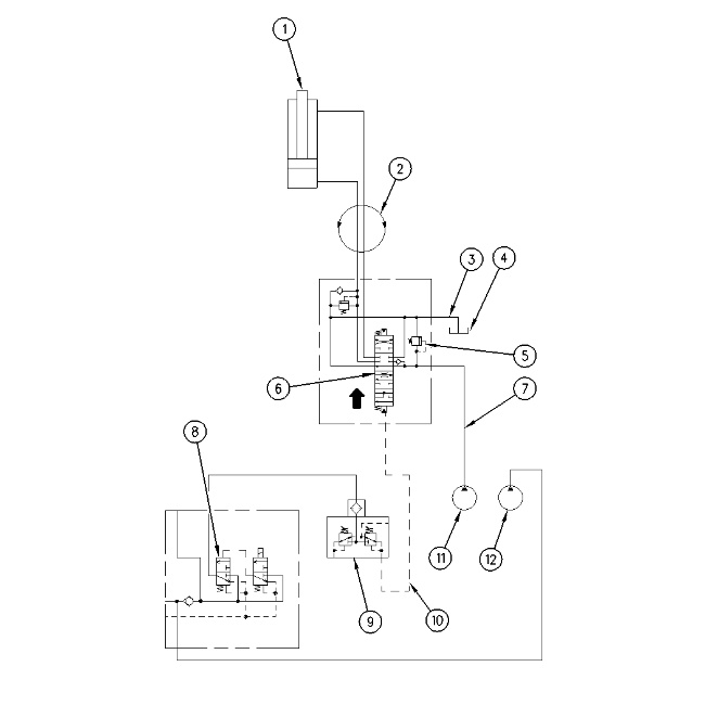
Hydraulic Schematic For Blade Lower
|
|
|
|
|
|
| Illustration 1 | g00758273 |
|
(1) Blade cylinder (2) Swivel (3) Return line (4) Hydraulic tank (5) Main relief valve (6) Blade control valve (7) Delivery line (8) Hydraulic activation control valve (9) Pilot control valve (10) Pilot line (11) Blade pump (12) Pilot pump |
|
Control Of Blade
Introduction
|
|
|
|
|
|
| Illustration 2 | g00869437 |
|
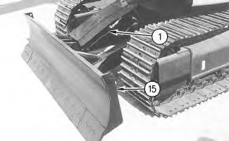
(1) Blade cylinder (15) Blade |
|
Blade (15) is attached to the front of the undercarriage. The blade is mainly used for levelling work.
|
|
|
|
|
|
| Illustration 3 | g00869446 |
|
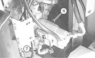
(7) Delivery line (11) Blade pump |
|
Blade cylinder (1) is driven by the oil delivery from blade pump (11). The supply oil flows through delivery line (7) to blade control valve (6).
|
|
|
|
|
|
| Illustration 4 | g00869457 |
|
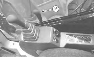
(16) Blade control lever |
|
|
|
|
|
|
|
| Illustration 5 | g00869498 |
|
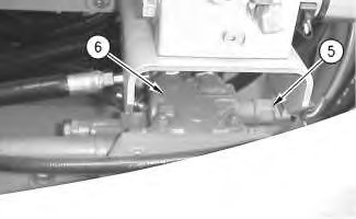
(5) Blade main relief valve (6) Blade control valve |
|
Blade control lever (16) controls the movement of blade (15). The control lever controls the following four positions of the blade: RAISE, LOWER, NEUTRAL and FLOAT. Levelling work is accomplished by using the mass (weight and size) of the blade in the FLOAT position.
Blade cylinder (1) extends or blade cylinder retracts by moving the blade control lever. When blade control lever (16) is moved to the LOWER position, oil from blade pump (11) flows through line (7) into blade control valve (6). The oil flows out of blade control valve (6) and flows through swivel (2) to the head end of blade cylinder (1). The blade cylinder extends for the LOWER position.
When blade control lever (16) is placed in the NEUTRAL position, oil to blade cylinder (1) is blocked. In this position, the blade (15) can be used as a stabilizer. The circuit pressure for the blade is limited to 20600 kPa (2990 psi) by main relief valve (5) .
Blade LOWER
|
|
|
|
|
|
| Illustration 6 | g00437170 |
|
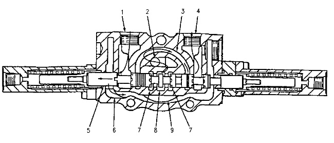
Blade control valve (LOWER position) (1) Port (2) Passage (3) Passage (4) Port (5) Stem (6) Return passage (7) Passage (8) Center bypass passage (9) Return passage |
|
When the blade control lever is moved forward to the LOWER position, stem (5) shifts to the left in order to lower the blade.
When stem (5) shifts to the left, the oil from the blade pump from center bypass passage (8) flows through passages (2) and (3). The oil then enters port (4). The oil flows out of the blade control valve and flows to the head end of the blade cylinder. This causes the blade to lower.
Return oil from the blade cylinder enters port (1). The return oil flows through passage (6) and passage (9). The oil then flows back to the hydraulic tank.
Blade RAISE
When the blade control lever is moved backward from the NEUTRAL position, stem (5) shifts to the right. The blade control valve sends oil from the blade pump to the rod end of the blade cylinder. This causes the blade to RAISE.
Blade FLOAT
|
|
|
|
|
|
| Illustration 7 | g00437931 |
|
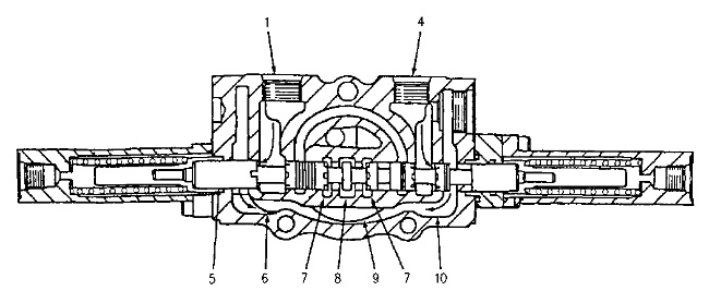
Blade control valve (FLOAT position) (1) Port (4) Port (5) Stem (6) Return passage (7) Passage (8) Center bypass passage (9) Return passage (10) Return passage |
|
In the FLOAT position, no pump oil is supplied to the blade cylinder. No hydraulic control is used on the blade cylinder. The mass (size and weight) of the blade causes the blade to stay on the ground. The FLOAT position is suitable for levelling work on a soft surface.
When the blade control lever is moved forward into the detent position, the blade is placed in the FLOAT position. Stem (5) shifts to the left and passage (7) opens. Oil from the blade pump enters center bypass passage (8) and flows through passage (7) to return passage (9) .
Oil in the blade cylinder flows through return passage (9) in one of two ways. The oil returns through port (1) and passage (6) and back to the hydraulic tank or the oil returns through port (4) and passage (10) and back to the hydraulic tank.
