|
|
|
|
|
|
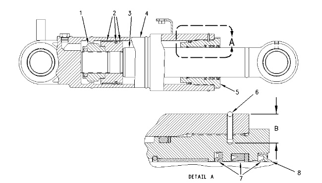
| Illustration 1 | g00743793 |
(1) Torque of locknut with lubricant on the threads … 2800 ± 140 N·m (2060 ± 105 lb ft)
Width across flats … 89.3 mm (3.52 inch)
(2) Before you install the seal assembly, fill the clearances with grease in order to remove the air.
(3) Diameter of new rod assembly … 79.93 ± 0.03 mm (3.147 ± 0.001 inch)
(4) Bore of new cylinder assembly … 120.0 ± 0.10 mm (4.72 ± 0.004 inch)
(5) Cylinder head
- Bore of new cylinder head … 80.63 ± .03 mm (3.174 ± 0.0012 inch)
- Torque for the cylinder head … 1100 ± 110 N·m (820 ± 80 lb ft)
Drill a hole 4.5 mm (0.177 inch) in diameter to the depth of dimension (C). Backup ring (6) fits in the hole. Dimension (B) … 23.0 ± 0.5 mm (0.91 ± 0.02 inch)
(6) Apply 4C-9502 Gasket Sealant in the hole for the backup ring.
(7) Lubricate the sealing lip slightly with the lubricant that is being sealed before installation.
(8) Apply 4C-4032 Bearing Mount Compound to the seal ring groove before installation of the seal.
Blade Cylinder Drift Rate
Raise the oil temperature to 55° ± 5°C (131° ± 9° F).
The maximum permissible drift for a new cylinder is 9 mm (0.35 inch) over a three minute period of time.
