Installation Procedure
Note: Check the O-ring seals, the gaskets, and the seals for wear or for damage. Replace the components, if necessary.
|
|
| NOTICE |
|---|
|
Care must be taken to ensure that fluids are contained during performance of inspection, maintenance, testing, adjusting and repair of the product. Be prepared to collect the fluid with suitable containers before opening any compartment or disassembling any component containing fluids. Refer to Special Publication, NENG2500, “Caterpillar Tools and Shop Products Guide” for tools and supplies suitable to collect and contain fluids on Caterpillar products. Dispose of all fluids according to local regulations and mandates. |
|
|
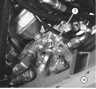
- Install control manifold (7) through the opening on the underside of the machine. Position control manifold (7) for installation on the bracket assembly. Install four bolts (14) .
|
|
|
|
|
|
| Illustration 1 | g00889327 |
|
The above Illustration is taken from the underside of the machine. |
|
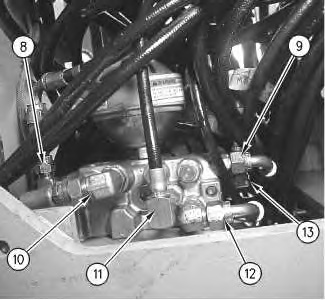
- Install hose assembly (13). Tighten hose assembly (13) to a torque of 25 ± 3 N·m (18 ± 2 lb ft).
|
|
|
|
|
|
| Illustration 2 | g00889303 |
|
The above Illustration is taken from the underside of the machine. |
|
- Install hose assembly (12). Tighten hose assembly (12) to a torque of 37 ± 4 N·m (27 ± 3 lb ft).
- Install hose assembly (11). Tighten hose assembly (11) to a torque of 25 ± 3 N·m (18 ± 2 lb ft).
- Install hose assembly (10). Tighten hose assembly (10) to a torque of 76 ± 4 N·m (56 ± 3 lb ft).
- Install hose assembly (9). Tighten hose assembly (9) to a torque of 37 ± 4 N·m (27 ± 3 lb ft).
- Install hose assembly (8). Tighten hose assembly (8) to a torque of 37 ± 4 N·m (27 ± 3 lb ft).
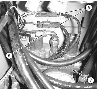
- Connect hose assembly (6) to control manifold (7). Tighten hose assembly (6) to a torque of 37 ± 4 N·m (27 ± 3 lb ft). Slide connectors for harness assemblies (5) into the mounting locations. Connect harness assemblies (5) .
|
|
|
|
|
|
| Illustration 3 | g00889255 |
|
The above Illustration is taken from the top side of control manifold (7) . |
|
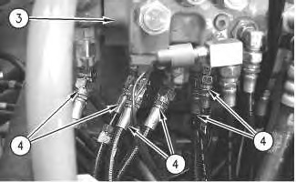
- Connect hose assemblies (4) to the main control valve.
|
|
|
|
|
|
| Illustration 4 | g00889193 |
|
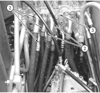
The above Illustration is from the top side of the machine. |
|
- Connect hose assemblies (2) to main control valve (3) .
|
|
|
|
|
|
| Illustration 5 | g00888919 |
|
The above Illustration is taken from the top side of the machine. |
|
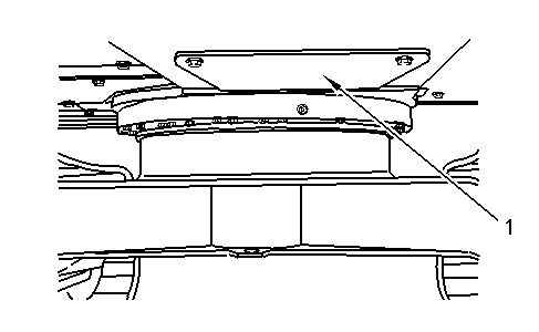
- Install bottom guard (1) .
|
|
|
|
|
|
| Illustration 6 | g00889074 |
|
Bottom guard (1) is located at the rear of the swing gear. |
|
- Fill the hydraulic system. Refer to Operation and Maintenance Manual, “Hydraulic System Oil – Change” for the proper procedure. Refer to Operation and Maintenance Manual, “Refill Capacities”.
