|
|
|
|
|
|
| Illustration 1 | g00802556 |
|
Location of stick lowering control valve (1) Stick cylinder (2) Stick lowering control valve |
|
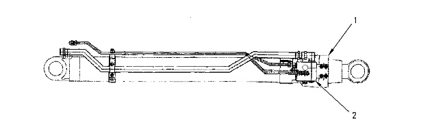
The stick lowering control valve is located on the head end of the stick cylinder.
The stick lowering control valve prevents the stick from falling if a hydraulic supply line fails or if a supply tube to the stick cylinder fails.
Note: The stick lowering control valve is supplied only when there is a boom lowering control valve.
|
|
|
|
|
|
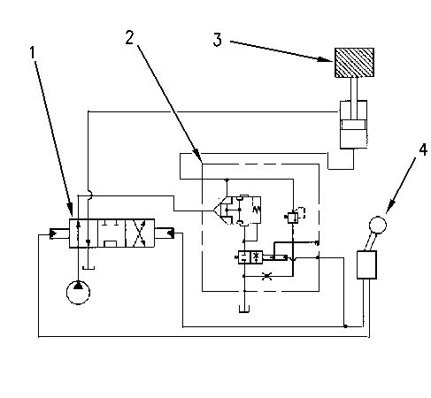
| Illustration 2 | g00795530 |
|
Simplified hydraulic schematic (stick lowering control valve) (1) Main control valve (2) Stick lowering control valve (3) Stick cylinder (4) Joystick |
|
STICK OUT Operation
|
|
|
|
|
|
| Illustration 3 | g00795501 |
|
(1) Main control valve (2) Stick lowering control valve (3) Stick cylinder (4) Joystick (5) Inlet port (6) Sealing face (7) Outlet port to head end of stick cylinder (8) Spool 1 (9) Chamber |
|
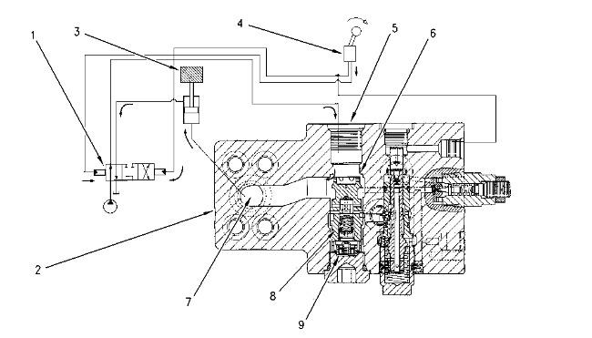
When joystick (4) is moved to the STICK OUT position, the pump oil flows from main control valve (1) to stick lowering control valve (2). The pump oil flows through port (5). This will move spool (8) downward. Pump oil then flows through the passage to port (7) and to the head end of stick cylinder (3) .
STICK IN Operation
|
|
|
|
|
|
| Illustration 4 | g00795502 |
|
(1) Main control valve (2) Stick lowering control valve (3) Stick cylinder (4) Joystick (5) Inlet port (7) Outlet port to head end of stick cylinder (8) Spool 1 (9) Chamber (10) Passage to drain (11) Piston (12) Inlet port for pilot oil (13) Chamber (14) Spool 2 (15) Relief valve |
|
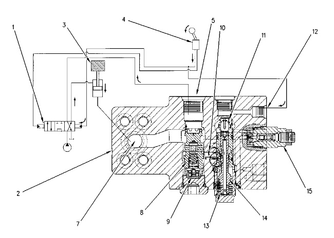
When joystick (4) is moved to the STICK IN position, pilot oil flows from joystick (4) to port (12). This will move piston (11) downward. When piston (11) moves downward, hydraulic oil from chamber (9) flows through passage (10). This will allow spool (8) to open. Hydraulic oil then flows from port (7) to port (5) and back to the tank. This allows the stick to move inward.
Stick Hold
|
|
|
|
|
|
| Illustration 5 | g00795503 |
|
(4) Joystick (5) Inlet port (6) Sealing face (7) Outlet port to head end of stick cylinder (8) Spool 1 (9) Chamber |
|

When joystick (4) is moved to the NEUTRAL position, the stick cylinder is held in the raised position. This allows spool (8) to move upward due to spring force in chamber (9). Spool (8) will then seal against sealing face (6). Spool (8) prevents oil from leaking from port (7) to port (5) .
Relief Operation of the Cylinder Head End
|
|
|
|
|
|
| Illustration 6 | g00795592 |
|
(1) Main control valve (2) Stick lowering control valve (3) Stick cylinder (4) Joystick (5) Inlet port (7) Outlet port to head end of stick cylinder (8) Spool 1 (9) Chamber (10) Passage to drain (11) Piston (12) Inlet port for pilot oil (13) Chamber (14) Spool 2 (15) Relief valve (16) Chamber |
|
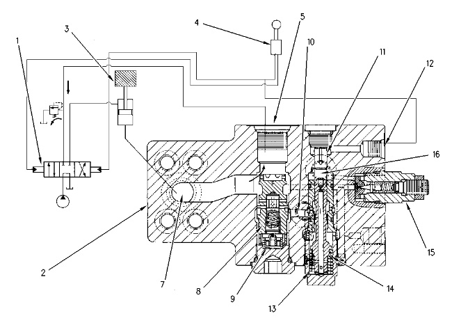
When the stick is pushed inward by an outside force, the oil pressure in port (7) increases. The oil pressure is sensed at relief valve (15). When oil pressure overcomes the relief valve setting, the relief valve allows oil to fill chamber (16). The oil pressure in chamber (16) moves spool (14) downward. Oil then flows from chamber (9) to passage (10). This will allow spool (8) to open. Hydraulic oil will then flow from port (7) to port (5) and back to the tank. This lowers the hydraulic oil pressure until the hydraulic oil pressure is lower than the relief valve setting.