Installation Procedure
| Required Tools | |||
|---|---|---|---|
| Tool | Part Number | Part Description | Qty |
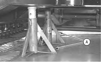
| A | 5P-6215 | Jack Stand | 2 |
|
|
| NOTICE |
|---|
|
Care must be taken to ensure that fluids are contained during performance of inspection, maintenance, testing, adjusting and repair of the product. Be prepared to collect the fluid with suitable containers before opening any compartment or disassembling any component containing fluids. Refer to Special Publication, NENG2500, “Caterpillar Tools and Shop Products Guide” for tools and supplies suitable to collect and contain fluids on Caterpillar products. Dispose of all fluids according to local regulations and mandates. |
|
|
- Thoroughly clean all mating surfaces prior to installation.
- Raise the side of the machine and install Tooling (A) under the frame.
|
|
|
|
|
|
| Illustration 1 | g00538695 |
Note: Adjust the height of Tooling (A) so that there is enough clearance between the sprocket and track links for installation of the final drive and travel motor.
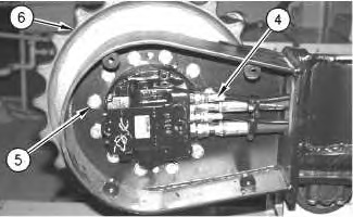
- Attach a suitable lifting device to final drive and travel motor assembly (6). Install the final drive and the travel motor into the undercarriage frame. The weight of the final drive and travel motor is approximately 118 kg (260 lb).
|
|
|
|
|
|
| Illustration 2 | g00538828 |
- Apply 9S-3263 Thread Lock Compound on the threads of twelve bolts (5). Install bolts (5). Tighten the bolts to a torque of 270 ± 40 N·m (200 ± 30 lb ft).
- Replace the O-ring seals in the ends of hose assemblies (4) with new O-ring seals.
- Connect hose assemblies (4).
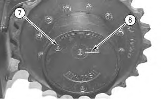
- Fill the final drive with oil. Refer to Operation and Maintenance Manual, SEBU7421, “Final Drive Oil – Change” for the proper procedure.
|
|
|
|
|
|
| Illustration 4 | g00539286 |
- Fill the hydraulic tank with oil. Refer to Operation and Maintenance Manual, SEBU7421, “Hydraulic Oil Level – Check”.
End By:
Connect the track. Refer to Disassembly and Assembly, “Track – Connect”.


