Removal Procedure
| Required Tools | |||
|---|---|---|---|
| Tool | Part Number | Part Description | Qty |
| A | 5P-6215 | Jack Stand | 2 |
Start By:
- Separate the track. Refer to Disassembly and Assembly, “Track – Separate”.
|
At operating temperature, the hydraulic oil is hot and under pressure. Hot oils can cause burns. To prevent possible personal injury, release the pressure in the implement hydraulic circuit (boom, stick, bucket, and swing), travel circuits, and the hydraulic oil tank at the filler cap before any hydraulic lines or components are disconnected or removed. Remove the filler cap only when the engine is stopped and the filler cap is cool enough to touch. |
|
|
| NOTICE |
|---|
|
Care must be taken to ensure that fluids are contained during performance of inspection, maintenance, testing, adjusting and repair of the product. Be prepared to collect the fluid with suitable containers before opening any compartment or disassembling any component containing fluids. Refer to Special Publication, NENG2500, “Caterpillar Tools and Shop Products Guide” for tools and supplies suitable to collect and contain fluids on Caterpillar products. Dispose of all fluids according to local regulations and mandates. |
|
|
Note: Put identification marks on all hose assemblies for installation purposes. Plug all hose assemblies. This helps to prevent fluid loss, and this helps to keep contaminants from entering the system.
- Raise the side of the machine and install Tooling (A) under the frame.
|
|
|
|
|
|
| Illustration 1 | g00538695 |
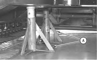
Note: Adjust the height of Tooling (A) so that there is enough clearance between the sprocket and track links for removal of the final drive and motor.
- Rotate the final drive until drain plug (1) is at the bottom. Drain the oil into a suitable container for storage or disposal. The capacity of the final drive assembly is 1.7 L (0.5 US gal).
|
|
|
|
|
|
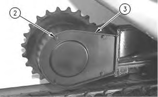
| Illustration 2 | g00538723 |

- Release the hydraulic system pressure. Refer to Disassembly and Assembly, “Hydraulic System Pressure – Release”.
- Remove four bolts (2) and cover (3) from the rear of the undercarriage frame.
|
|
|
|
|
|
| Illustration 3 | g00538793 |