Disassembly Procedure
Start By:
- Remove the main control valve. Refer to the Disassembly and Assembly Manual, “Main Control Valve – Remove” for the procedure.
Note: Cleanliness is an important factor. Before beginning the disassembly procedure, thoroughly clean the exterior of the component. This will help prevent dirt from entering the internal mechanism. The precision components in the hydraulic system can be damaged by contaminants or by dirt. All disassembly procedures must be performed on a clean work surface. Clean all of the internal components with clean solvent. Dry all of the internal components with compressed air. Plug the ports and plug the hose assemblies on the machine during the repair.
Note: Put identification marks on all of the components of the main control valve as the components are being removed. All of the components must be installed in the original locations and in the original orientations. Keep all of the internal parts of the main control valve clean and lubricated.
Note: Carefully inspect all O-ring seals. Replace any O-ring seals that are worn or damaged.
Note: Machines may be equipped with attachments that have valve configurations which differ from the example in this procedure.
|
|
| NOTICE |
|---|
|
Keep all parts clean from contaminants. Contamination of the hydraulic system with foreign material will reduce the service life of the hydraulic system components. To prevent contaminants from entering the hydraulic system, always plug or cap the lines, fittings, or hoses as they are disconnected. Cover any disassembled components and clean them properly before assembly. Clean the hydraulic system properly after any major component exchange or especially after a component failure, to remove any contamination. |
|
|
|
Personal injury can result from being struck by parts propelled by a released spring force. Make sure to wear all necessary protective equipment. Follow the recommended procedure and use all recommended tooling to release the spring force. |
Attachment Control Valve (If Equipped)
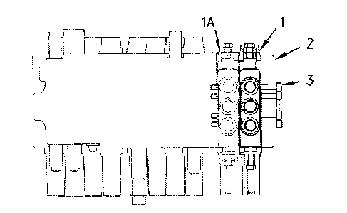
- Remove bolts (3), cover (2) and attachment control valves (1) and (1A) .
|
|
|
|
|
|
| Illustration 1 | g00878426 |
|
Two attachment control valves are illustrated. |
|
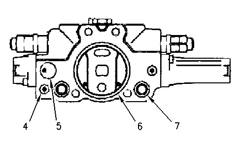
- Remove O-ring seals (4), (5), (6), and (7) from the attachment control valve.
|
|
|
|
|
|
| Illustration 2 | g00878651 |
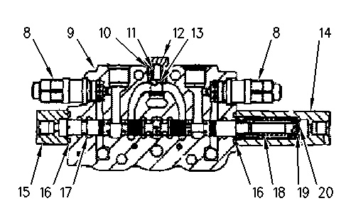
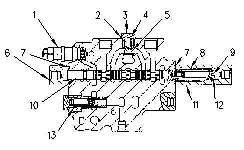
- Remove two relief valves (8) from housing (9). One relief valve is located on the top of the attachment control valve. The second relief valve is located on the bottom of the attachment control valve.
|
|
|
|
|
|
| Illustration 3 | g00878612 |
- Carefully remove plug (12) and remove O-ring seal (10) from the plug. Remove spring (11) and remove valve (13) .
|
Personal injury can result from being struck by parts propelled by a released spring force. Make sure to wear all necessary protective equipment. Follow the recommended procedure and use all recommended tooling to release the spring force. |
- Remove the bolts, cover (15), and O-ring seal (16). Remove the bolts, cover (14), and O-ring seal (16) .
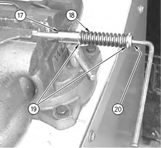
- Remove spool (17), spring (18), seat (19), and rod (20) as a unit. Use an Allen wrench to remove rod (20) from spool (17). Remove seat (19) and remove spring (18) from the spool. Remove the remaining seat (19) from the spool.
|
Personal injury can result from being struck by parts propelled by a released spring force. Make sure to wear all necessary protective equipment. Follow the recommended procedure and use all recommended tooling to release the spring force. |
|
|
|
|
|
|
| Illustration 4 | g00878874 |
Main Control Valve
|
|
|
|
|
|
| Illustration 5 | g00878889 |
|
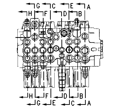
(A-A) Stick 1 Valve (B-B) Swing Valve (C-C) Travel Valve (D-D) Straight Travel Valve (E-E) Travel Valve (F-F) Option Valve (G-G) Boom 1 Valve (H-H) Bucket Valve |
|
Stick 1 Valve
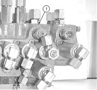
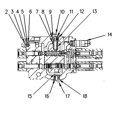
- Remove the bolts and plate (2). Remove two O-ring seals (3), ring (4), O-ring seal (5), and spacer (6) .
|
|
|
|
|
|
| Illustration 6 | g00878435 |
|
|
|
|
|
|
| Illustration 7 | g00878939 |
- Remove plug (10). Remove O-ring seal (9) from the plug. Remove spring (8) and remove valve (7). Remove spring (11), valve (12), and sleeve (13) .
|
Personal injury can result from being struck by parts propelled by a released spring force. Make sure to wear all necessary protective equipment. Follow the recommended procedure and use all recommended tooling to release the spring force. |
- Remove relief valve (14) from the housing (1) .
- Carefully remove plug (17) and remove O-ring seal (18) from the plug. Remove spring (16) and remove valve (15) .
|
Personal injury can result from being struck by parts propelled by a released spring force. Make sure to wear all necessary protective equipment. Follow the recommended procedure and use all recommended tooling to release the spring force. |
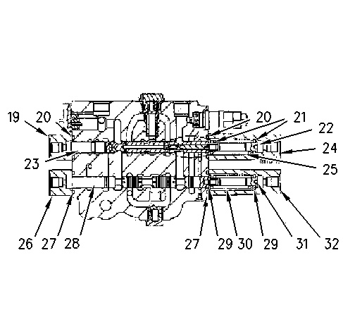
- Remove the bolts, cover (19), and O-ring seal (20). Remove the bolts, cover (24), and O-ring seal (20).
|
|
|
|
|
|
| Illustration 8 | g00885668 |
- Carefully remove spool (23), spring (25), seats (21), and rod (22) as a unit. Use an Allen wrench to remove rod (22) from spool (23). Remove seat (21) and remove spring (25) from the spool. Remove the remaining seat (21) from the spool.
|
Personal injury can result from being struck by parts propelled by a released spring force. Make sure to wear all necessary protective equipment. Follow the recommended procedure and use all recommended tooling to release the spring force. |
- Remove bolts, cover (26), and O-ring seal (27). Remove the bolts, cover (32), and O-ring seal (27).
- Carefully remove spool (28), spring (30), seats (29), and rod (31) as a unit. Use an Allen wrench to remove rod (31) from spool (28). Remove seat (29) and remove spring (30) from the spool. Remove the remaining seat (29) from the spool.
|
Personal injury can result from being struck by parts propelled by a released spring force. Make sure to wear all necessary protective equipment. Follow the recommended procedure and use all recommended tooling to release the spring force. |
Swing Valve
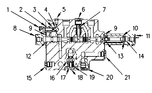
- Carefully remove plug (3) and remove O-ring seal (2) from the plug. Remove spring (4) and remove valve (5) .
|
Personal injury can result from being struck by parts propelled by a released spring force. Make sure to wear all necessary protective equipment. Follow the recommended procedure and use all recommended tooling to release the spring force. |
- Remove the bolts, cover (6), and O-ring seal (7). Remove the bolts, cover (11), and O-ring seal (7) .
- Remove spool (10), spring (8), seats (12), and rod (9) as a unit. Use an Allen wrench to remove rod (9) from spool (10). Remove seat (12) and remove spring (8) from the spool. Remove the remaining seat (12) from the spool.
|
Personal injury can result from being struck by parts propelled by a released spring force. Make sure to wear all necessary protective equipment. Follow the recommended procedure and use all recommended tooling to release the spring force. |
Travel
- Remove plug (5). Remove plug (6) and sleeve (7) .
- Remove the bolts, cover (8), and O-ring seal (9). Remove the bolts, cover (11), and O-ring seal (9) .
