|
|
|
|
|
|
| Illustration 1 | g01030058 |
|
Hydraulic schematic of pump system (1) Left travel motor (2) Right travel motor (3) Swing motor (4) Bucket cylinder (5) Boom cylinder (6) Stick cylinder (7) Blade cylinder (8) Swivel (9) Blade control valve (10) Main control valve (11) Pilot control valve (travel) (12) Boom drift reduction valve (13) Main relief valve (14) Slow return check valve (15) Bypass check valve (16) Oil cooler (17) Accumulator (18) Solenoid valve (travel speed) (19) Solenoid valve (hydraulic activation) (20) Right pump (21) Left pump (22) Pilot oil manifold (23) Pilot pump (24) Blade pump (25) Pilot relief valve (26) Pilot filter (27) Hydraulic tank (28) Pilot control valve (swing and stick) (29) Pilot control valve (boom and bucket) (30) Pilot control valve (blade) |
|

This machine is driven and controlled by the following three systems:
- The Main Hydraulic System
The main hydraulic system provides oil to the cylinders of the machine and to the motors of the machine.
- The Blade Hydraulic System
The blade hydraulic system provides oil to the blade circuits.
- The Pilot Hydraulic System
The pilot hydraulic system provides oil to the control circuits.
Hydraulic Pump Flow and Pressure Control System
|
|
|
|
|
|
| Illustration 2 | g00864458 |
|
Pump compartment (23) Pilot pump (24) Blade pump (31) Main pump |
|
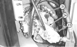
The main hydraulic system is driven by main pump (31). The main pump is a single piston type pump. The pump is a variable displacement pump. The main pump functions as a double pump by splitting the pump flow into the right circuit and the left circuit. This splitting of the flow is accomplished by the activation of the pistons in the cylinder block.
Note: For additional information on the division of pump flow, refer to the section on Pump Operation in this module.
Throughout this module, the part of the main pump that supplies oil to the right circuits will be referred to as the “right pump”. The part of the main pump that supplies oil to the left circuits will be referred to as the “left pump”. The right pump supplies oil to the right control system of main control valve (10). The left pump supplies oil to the left control system of main control valve (10). The main pump is connected mechanically to the engine through a flexible coupling.
The gear type pump (blade) (24) is directly connected to the rear of the main pump. Pressure oil from the gear pump is supplied to the hydraulic circuits for the blade. The gear type pilot pump (23) is directly connected to the rear of the blade pump. Pressure oil from gear pump (23) is supplied to the pilot hydraulic circuits. All of the engine output is used for driving the main pump, the blade pump, and the pilot pump.
The delivery pressure of the main pump increases according to the load on the machine. As the load increases, the delivery pressure increases and the flow decreases. As pressure increases or pressure decreases, the hydraulic horsepower remains equal to the engine horsepower. (See Systems Operation, “Pump Control (Main Hydraulic)”.)
Oil that is delivered from right pump (20) and left pump (21) enters control valve (10). If no work is performed, the pump oil passes through the main control valve and flows to hydraulic tank (27). If an operation is being performed, the control valve directs pump oil to the travel motors, the swing motor, and the cylinders.
The main control valve contains spools, check valves, relief valves, and orifices. These valves and orifices allow single operations to be performed. The valves and orifices also allow a combination of operations to be performed at the same time. The maximum working pressure of the main hydraulic system is restricted by the main relief valve (13). The main relief valve setting is 32000 kPa (4640 psi) during travel operation and 28000 kPa (4060 psi) during implement operation or swing operation.
The flow of oil from pilot pump (23) does not depend on oil pressure. The pump delivers a constant flow to the pilot circuit. The maximum pressure in the pilot circuits is restricted by pilot relief valve (25) to 4200 kPa (610 psi).
Note: For further information on the pilot control system, refer to Systems Operation, “Pilot Hydraulic System”.
|
|
|
|
|
|
| Illustration 3 | g00864462 |
|
Blade control valve (32) Inlet line (33) Blade relief valve |
|
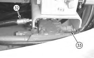
The oil that is delivered from blade pump (24) enters blade control valve (9) through inlet line (32). When the blade control lever is in the neutral position the oil passes through the blade control valve and flows back to hydraulic tank (27).
The maximum working pressure of the blade hydraulic system is restricted by the blade relief valve (33) to 25000 kPa (3625 psi).