| Required Tools | ||
|---|---|---|
| Part Number | Description | Qty |
| 8T-0861 | Pressure Gauge ( 60000 kPa (8700 psi)) |
2 |
Note: A temporary setting of the main relief valve pressure is required before any line relief valve pressure setting is adjusted. Refer to Testing and Adjusting, “Relief Valve (Main) – Test and Adjust”.
Preparation
- Position the machine on level ground.
- Stop the engine.
- Release the pressure in the hydraulic system. Refer to Testing and Adjusting, “Hydraulic System Pressure – Release”.
- Connect a 60000 kPa (8700 psi) pressure gauge to pressure tap (1). This is used to monitor the line relief valve pressure setting of the stick cylinder.
|
|
|
|
|
|
| Illustration 1 | g00858167 |
|
Pump compartment (1) Pressure tap (right pump delivery pressure) (2) Pressure tap (left pump delivery pressure) |
|

- Connect a 60000 kPa (8700 psi) pressure gauge to pressure tap (2). This is used to monitor the line relief valve pressure setting of the boom cylinders and the bucket cylinder.
|
|
|
|
|
|
| Illustration 2 | g00858357 |
|
Main control valve (front view) (9) Line relief valve (stick cylinder head end) (10) Line relief valve (boom cylinder rod end) (11) Line relief valve (bucket cylinder head end) (12) Line relief valve (stick cylinder rod end) (13) Line relief valve (boom cylinder head end) |
|
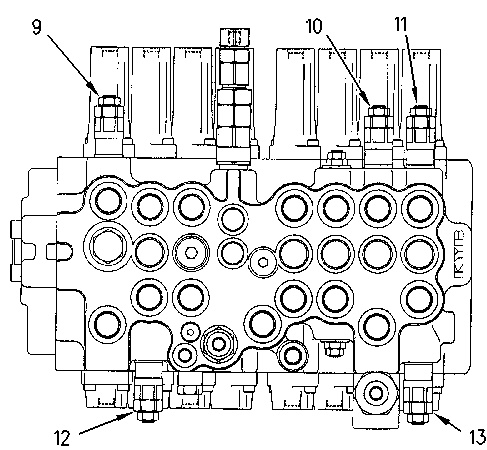
The following line relief valves are located on top of the main control valves: stick cylinder head end (9), boom cylinder rod end (10) and bucket cylinder head end (11). Line relief valve (12) for the stick cylinder rod end and line relief valve (13) for the boom cylinder head end are located on the bottom of the main control valve.
|
|
|
|
|
|
| Illustration 3 | g00858372 |
|
Line relief valve (typical example) (14) Locknut (15) Adjustment screw |
|
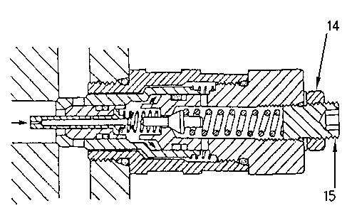
Note: Turn adjustment screw (15) clockwise in order to increase the pressure. Turn adjustment screw (15) counterclockwise in order to decrease the pressure.
Note: Always make final pressure adjustment on pressure rise.
Note: Return the main relief valve pressure to the specified setting after testing and adjusting any line relief valve. Refer to Testing And Adjusting, “Relief Valve (Main) – Test and Adjust” for the main relief valve pressure setting.
Adjustment (Boom Cylinders)
- To adjust the line relief valve pressure setting of the boom cylinder head end, move the joystick for the boom until the boom is at the full BOOM RAISE position (full extension of boom cylinders). Hold the joystick for the boom in this position.
- Check the pressure in the boom cylinder head end on the pressure gauge at pressure tap (2) .
- Return the joystick for the boom to the NEUTRAL position.
- The pressure gauge reading should be 31000 ± 1500 kPa (4500 ± 215 psi). If the pressure gauge reading at pressure tap (2) is not within the specification, adjust the line relief valve.
- Loosen locknut (14) on boom line relief valve (13). Turn adjustment screw (15) until the pressure gauge reading at pressure tap (2) is 31000 ± 1500 kPa (4500 ± 215 psi).
Note: Always make final pressure adjustment on pressure rise.
- To adjust the line relief valve pressure setting of the boom cylinder rod end, move the joystick for the boom until the boom is at the full BOOM LOWER position (full retraction of boom cylinders). Hold the joystick for the boom in this position.
Note: Use engine low idle speed in order to adjust the line relief valve pressure setting of the boom cylinder rod end. Refer to Testing and Adjusting, “Engine Performance – Test” for engine rpm settings.
- Check the pressure in the boom cylinder rod end on the pressure gauge at pressure tap (2) .
- Return the joystick for the boom to the NEUTRAL position.
- The pressure gauge reading should be 31000 ± 1500 kPa (4500 ± 215 psi). If the pressure gauge reading at pressure tap (2) is not within the specification, adjust the line relief valve.
- Loosen locknut (14) on boom line relief valve (10). Turn adjustment screw (15) until the pressure gauge reading at pressure tap (2) is 31000 ± 1500 kPa (4500 ± 215 psi).
Note: Always make final pressure adjustment on pressure rise.
- After completion of line relief valve adjustment, tighten locknut (14) to a torque of 30 ± 2 N·m (20 ± 1 lb ft).
Note: If an appropriate location is not available to fully extend the boom cylinders, exchange the functions of the boom line relief valves. Remove the line relief valve for the boom cylinder head end and the line relief valve for the boom cylinder rod end from the main control valve. Exchange the location in the main relief valve of the line relief valves. Adjust the pressure of the boom line relief valve that is now attached in the head end. After completion of line relief valve adjustment, return the respective line relief valves to the original locations.
Adjustment (Stick Cylinder)
- To adjust the line relief valve pressure setting of the stick cylinder rod end, move the joystick for the stick until the stick is at the full STICK OUT position (full retraction of stick cylinder). Hold the joystick for the stick in this position.
- Check the pressure in the stick cylinder rod end on the pressure gauge at pressure tap (1) .
- Return the joystick for the stick to the NEUTRAL position.
- The pressure gauge reading should be 31000 ± 1500 kPa (4500 ± 215 psi). If the pressure gauge reading at pressure tap (1) is not within the specification, adjust the line relief valve.
- Loosen locknut (14) on stick line relief valve (12). Turn adjustment screw (15) until the pressure gauge reading at pressure tap (1) is 31000 ± 1500 kPa (4500 ± 215 psi).
Note: Always make final pressure adjustment on pressure rise.
- After completion of line relief valve adjustment, tighten locknut (14) to a torque of 30 ± 2 N·m (20 ± 1 lb ft).
- To adjust the line relief valve pressure setting of the stick cylinder head end, move the joystick for the stick until the stick is at the full STICK IN position (full extension of stick cylinder). Hold the joystick for the stick in this position.
- Check the pressure in the stick cylinder head end on the pressure gauge at pressure tap (1) .
- Return the joystick for the stick to the NEUTRAL position.
- The pressure gauge reading should be 31000 ± 1500 kPa (4500 ± 215 psi). If the pressure gauge reading at pressure tap (1) is not within the specification, adjust the line relief valve.
- Loosen locknut (14) on stick line relief valve (9). Turn adjustment screw (15) until the pressure gauge reading at pressure tap (1) is 31000 ± 1500 kPa (4500 ± 215 psi).
Note: Always make final pressure adjustment on pressure rise.
- After completion of line relief valve adjustment, tighten locknut (14) to a torque of 30 ± 2 N·m (20 ± 1 lb ft).
Adjustment (Bucket Cylinder)
- To adjust the line relief valve pressure setting of the bucket cylinder head end, move the joystick for the bucket until the bucket is at the full BUCKET CLOSE position (full extension of bucket cylinder). Hold the joystick for the bucket in this position.
- Check the pressure in the bucket cylinder head end on the pressure gauge at pressure tap (2) .
- Return the joystick for the bucket to the NEUTRAL position.
- The pressure gauge reading should be 31000 ± 1500 kPa (4500 ± 215 psi). If the pressure gauge reading at pressure tap (2) is not within the specification, adjust the line relief valve.
- Loosen locknut (14) on bucket line relief valve (11). Turn adjustment screw (15) until the pressure gauge reading at pressure tap (2) is 31000 ± 1500 kPa (4500 ± 215 psi).
Note: Always make final pressure adjustment on pressure rise.
- After completion of line relief valve adjustment, tighten locknut (14) to a torque of 30 ± 2 N·m (20 ± 1 lb ft).