Main Relief Valve
|
|
|
|
|
|
| Illustration 1 | g00865892 |
|
Cross section of straight travel valve and main relief valve (1) Port (2) Straight travel control valve (3) Check valve (4) Check valve (5) Passage (6) Main relief valve (7) Port (8) Line (9) Line (10) Line (11) Passage (12) Passage (13) Passage (14) Control valve (15) Pilot line (16) Right pump (17) Left pump (18) Pilot pump |
|
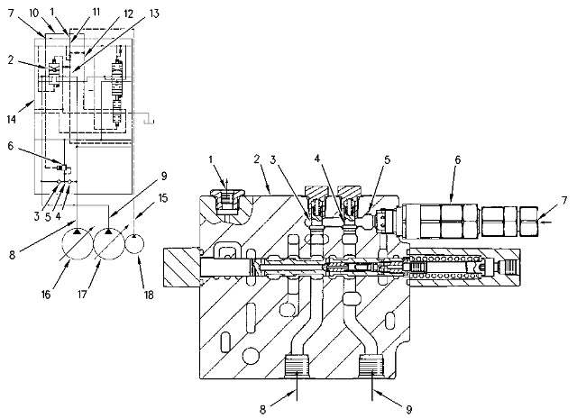
Oil from right pump (16) and left pump (17) enters main control valve (14) through lines (8) and (9). Right pump oil and left pump oil goes through check valves (3) and (4) to passage (5). The higher oil pressure from the right pump or the left pump goes through passage (5) to main relief valve (6) .
Pilot pump oil (18) is directed through line (15) and port (1) to passage (11). The oil from passage (11) is separated into passage (12) and passage (13). When the travel control is activated, passage (12) is blocked and oil from passage (11) flows only to passage (13). As a result, the pilot oil pressure in passage (12) will increase. When the implement control or the swing control are activated, pilot oil pressure in passage (13) increases in the same manner as travel control.
When the pressure in passage (12) increases, the setting pressure on the main relief pressure is changed in the following manner.
- When the control spool for travel is activated alone, the oil pressure in passage (12) increases. Increased oil pressure enters port (7) of main relief valve (6). The signal pressure activates so that the main relief valve opens at the circuit pressure of 32000 kPa (4640 psi) during a travel operation.
Closed Position
|
|
|
|
|
|
| Illustration 2 | g00865895 |
|
Main relief valve (valve In closed position) (5) Passage (19) Orifice (20) Spring chamber (21) Valve (22) Spring (23) Return passage (24) Valve (25) Passage (26) Spring |
|
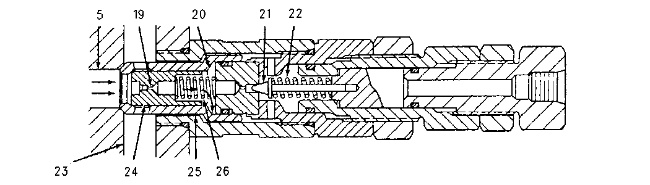
When main pump oil pressure in passage (5) is less than the main relief pressure setting, valve (21) is closed by the force of spring (22). The oil in passage (5) goes through orifice (19). Oil enters spring chamber (20). The pressure in passage (5) and the pressure in spring chamber (20) are equal. Valve (24) shifts left by the force of spring (26). Oil flow from passage (5) to return passage (23) is blocked.
Operation
|
|
|
|
|
|
| Illustration 3 | g00865893 |
|
Operation of main relief valve (valve in open position) (5) Passage (7) Port (10) Line (20) Spring chamber (21) Valve (22) Spring (23) Return passage (24) Valve (25) Passage (27) Piston (28) Passage |
|
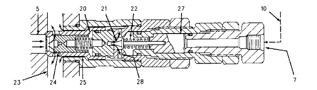
When the travel control is activated alone, pilot oil pressure that is in line (10) goes through port (7). This pilot oil pressure shifts piston (27). Piston (27) compresses spring (22). When the oil pressure in passage (5) increases to the relief valve pressure setting, valve (21) starts to shift to the right (open position) against the force of spring (22). The oil in spring chamber (20) goes through passages (28) and (25) to return passage (23). The oil pressure in spring chamber (20) becomes lower than the oil pressure in passage (5). This shifts valve (24) to the right (open position). Part of pressure oil in passage (5) flows to return passage (23). The oil pressure in passage (5) is now kept at the main relief valve pressure setting.
When implement control or swing control is activated, pilot oil pressure in line (10) decreases. Piston (27) is held stationary by spring (22). The force of spring (22) is now lower than the spring force during a travel operation. This allows the main relief valve to open during an implement operation and/or swing operation at a lower pressure than the main relief valve would open during a travel operation.
When the oil pressure in passage (5) increases to the relief valve pressure setting for implement circuits and/or swing circuits, valve (24) opens. Oil in passage (5) is allowed to flow into return passage (23) in the same manner as oil flows during a travel operation. The pressure in passage (5) is now kept at the main relief valve pressure setting for the implement operation and/or swing operation.