Hydraulic Activation Control Valve
|
|
|
|
|
|
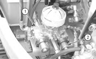
| Illustration 1 | g00869852 |
|
Pilot oil manifold (1) Pilot oil manifold (2) Solenoid valve (hydraulic activation) |
|
|
|
|
|
|
|
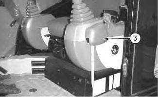
| Illustration 2 | g00869860 |
|
Inside cab (3) Hydraulic activation control lever (LOCKED position) |
|
|
|
|
|
|
|
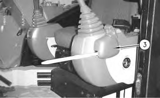
| Illustration 3 | g00869863 |
|
Inside cab (3) Hydraulic activation control lever (UNLOCKED position) |
|
|
|
|
|
|
|
| Illustration 4 | g00869857 |
|
Hydraulic activation control lever (3) Hydraulic activation control lever (4) Limit switch (5) Plunger |
|
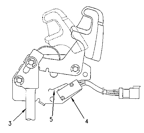
When hydraulic activation control lever (3) is placed in the LOCKED position, hydraulic activation solenoid valve (3) closes in order to block oil supply from the pilot pump to the pilot control valves. All hydraulic controls are blocked. No operation of the cylinders and the motors can be made by the activation of the hydraulic controls.
Hydraulic activation control lever (3) contains limit switch (4) and plunger (5). When plunger (5) on limit switch (4) is pushed, an electrical signal is sent to solenoid valve (2) .
The limit switch allows the engine start switch to operate only when hydraulic activation control lever (3) is placed in the LOCKED position. This prevents unexpected operation of the machine or the implement.
When hydraulic activation control lever (3) is placed in the UNLOCKED position, hydraulic activation solenoid valve (2) is energized by an electrical signal from limit switch (4) in order to allow pilot oil to flow to the pilot control valves.
|
|
|
|
|
|
| Illustration 5 | g00755306 |
|
Pilot manifold (hydraulic activation control valve) (7) Passage (11) Passage (12) Spring (13) Spool (14) Passage (15) Spring (16) Spool (17) Passage (18) Passage (19) Solenoid valve (20) Line |
|
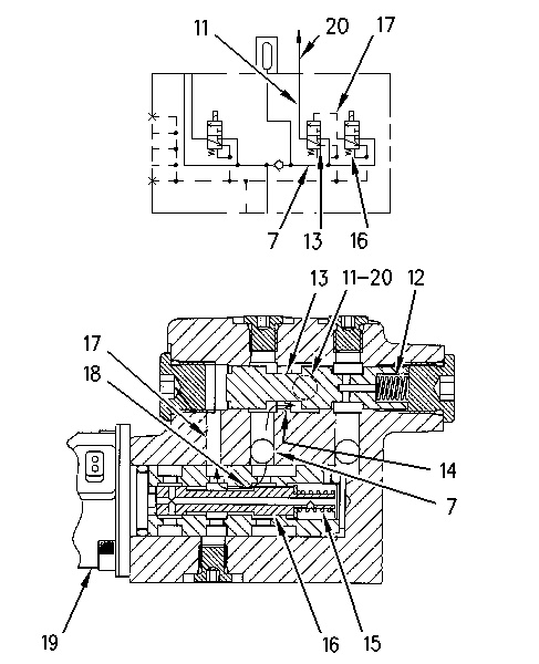
When hydraulic activation control valve (3) is placed in the UNLOCKED position, solenoid valve (19) is energized in order to move spool (16) to the right against the force of spring (15). This allows passage (18) to open. Pilot pressure oil flows through passage (7) and passage (18) to passage (17). The pressure oil acts against spool (13). Spool (13) shifts to the right against the force of spring (12). Passage (14) opens. Pilot pressure oil is sent to the pilot control valves through passage (11) and line (20). Limit switch (4) is turned ON as plunger (5) is pushed down by lever (3).
|
|
|
|
|
|
| Illustration 6 | g00755318 |
|
Pilot manifold (hydraulic activation control valve) (7) Passage (11) Passage (12) Spring (13) Spool (14) Passage (15) Spring (16) Spool (17) Passage (18) Passage (19) Solenoid valve (20) Line (21) Passage (22) Passage |
|
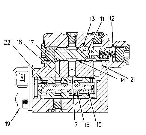
When hydraulic activation control lever (3) is in the LOCKED position, solenoid valve (19) is de-energized. Spool (16) returns to the left by the force of spring (15). Passage (22) opens. Oil in passage (17) drains and passage (18) closes. When the flow of pilot oil is blocked to passage (17), spool (13) is returned to the left by the force of spring (12). Passage (21) opens and passage (14) closes. Passage (7) and passage (11) are closed. Pilot oil supply to line (20) is stopped. Pilot oil supply to the pilot control valves (joysticks and travel levers/pedals) is blocked. The cylinders and the motors can not be activated.
With the hydraulic activation control lever (3) in the LOCKED position, limit switch (4) will turn OFF. Plunger (5) will become free from the lever.
The engine start switch can only be operated when limit switch (4) is in the OFF position and hydraulic activation control lever (3) is in the LOCKED position.