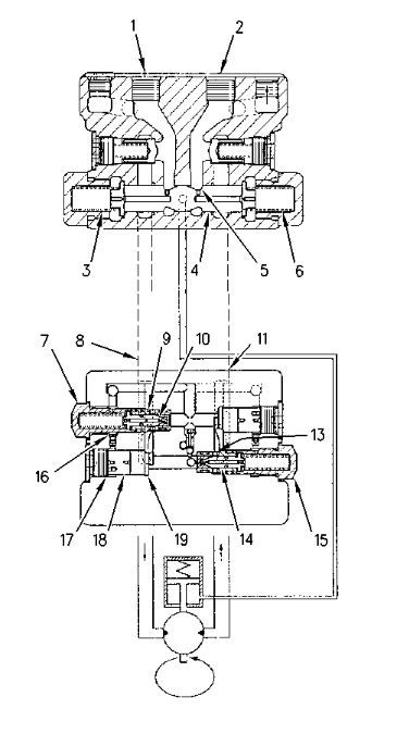
Counterbalance Valve
|
|
|
|
|
|
| Illustration 1 | g00757281 |
|
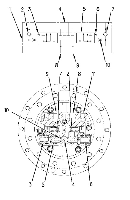
(1) Counterbalance valve (2) Check valve (3) Spring (4) Passage (parking brake) (5) Spool (counterbalance valve) (6) Spring (7) Check valve (8) Port (9) Port (10) Orifice (11) Cover (motor) |
|
Each travel motor contains a travel brake valve. The travel brake valve consists of counterbalance valve (1) and two check valves (2) and (7). The travel brake valve prevents the occurrence of a shock load during a travel stop. The travel brake valve also prevents cavitation and overrun. The travel brake valve sends oil to the parking brake in order to release the brake. This occurs before the start of the machine movement.
Counterbalance Valve Operation During Level Travel
|
|
|
|
|
|
| Illustration 2 | g00757283 |
|
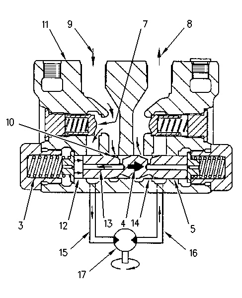
Counterbalance valve (level travel) (3) Spring (4) Passage (parking brake) (5) Spool (7) Check valve (8) Port (9) Port (10) Orifice (11) Cover (motor) (12) Spool chamber (13) Passage (14) Throttle slot (15) Passage (16) Passage (17) Motor rotary group |
|
Pump oil enters the counterbalance valve through port (9) and opens check valve (7). The oil then goes through passage (15) to motor rotary group (17). A portion of the pump oil from port (9) goes through orifice (10) of spool (5) and passage (13) into spool chamber (12). The oil pressure in spool chamber (12) shifts spool (5) to the right. Throttle slot (14) opens. Return oil from motor rotary group (17) flows through passage (16), through throttle slot (14) and through port (8). From port (8), the oil flows back to the hydraulic tank.
When spool (5) moves to the right, passage (4) opens. Oil flows from port (9) to the parking brake. The parking brake is released and the motor rotary group is allowed to rotate.
When pump oil is supplied through port (8), spool (5) moves to the left. The motor rotary group rotates in the reverse direction.
Counterbalance Valve Operation For Stopping The Machine
|
|
|
|
|
|
| Illustration 3 | g00757284 |
|
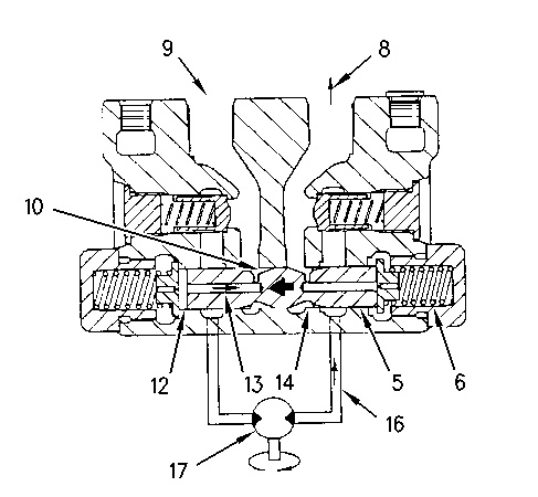
Counterbalance valve (travel stop) (5) Spool (6) Spring (8) Port (9) Port (10) Orifice (12) Spool chamber (13) Passage (14) Throttle slot (16) Passage (17) Motor rotary group |
|
When oil flow from port (9) is blocked, the pressure decreases in spring chamber (12). Spool (5) is returned to the left (NEUTRAL position) by the force of spring (6). When spool (5) returns, oil flow from spool chamber (12) is restricted at orifice (10) and passage (13). This restriction causes a slight pressure increase in spool chamber (12). This resistance causes slow movement of spool (5) to the NEUTRAL position. Throttle slot (14) closes at a controlled speed.
When no pump oil is supplied to port (9), the travel motor is still rotating because of the mass (weight and size) of the machine. Return oil flow from motor rotary group (17) flows through passage (16) and flows through throttle slot (14). The return oil flow is restricted at throttle slot (14). The rotation of the motor rotary group (17) slows at a controlled speed. When spool (5) is returned to the NEUTRAL position, throttle slot (14) closes completely. Return oil flow from the motor is blocked and the rotation of the motor stops smoothly.
When pump oil is blocked at port (8), spool (5) is returned to the right. The travel stops with minimal shock load.
Counterbalance Valve Operation During Slope Travel
|
|
|
|
|
|
| Illustration 4 | g00757285 |
|
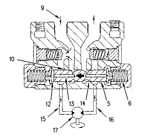
Counterbalance valve (slope travel) (5) Spool (6) Spring (9) Port (10) Orifice (12) Spool chamber (13) Passage (14) Throttle slot (15) Passage (16) Passage (17) Motor rotary group |
|
When the machine moves down a slope, the travel motors rotate at a higher speed. The higher speed is due to the mass of the machine. The pumps cannot maintain the oil supply to the motors. The lack of oil supply will cause cavitation in the travel motor. The pressure decreases at port (9). The oil pressure in spring chamber (12) and passage (15) decreases. Spring (6) forces spool (5) to the left. Throttle slot (14) starts closing. The return oil flow from motor rotary group (17) is restricted at throttle slot (14). The rotation of the travel motor will slow down.
The pump oil pressure at port (9) increases. The increased oil pressure goes through orifice (10) and passage (13) into spool chamber (12) .
The pressure oil in spool chamber (12) moves spool (5) to the right against the force of spring (6). Throttle slot (14) opens slightly. The oil pressure in passage (16) decreases. The modulation of spool (5) maintains the proper opening of throttle slot (14) during travel down a slope. The motor begins to rotate in accordance to pump oil supply. This prevents the motor from cavitating.
Operation Of Shock Reducing Valve
|
|
|
|
|
|
| Illustration 5 | g00757389 |
|
Shock reducing valve (1) Port (2) Port (3) Spool chamber (4) Spool (5) Passage (6) Spring (7) Shock reducing valve (8) Passage (9) Valve (10) Passage (11) Passage (13) Passage (14) Valve (15) Shock reducing valve (16) Passage (17) Piston chamber (18) Piston (19) Cover |
|
When the control lever is placed in the NEUTRAL position to stop the travel of the machine, oil supply to the travel motor and the brake valve is stopped.
When no oil is supplied from port (1), oil pressure in spool chamber (3) decreases. Spring (6) moves spool (4) to the left (neutral). However, the travel motor continues to rotate due to the mass (weight and size) of the machine. The return oil is blocked because passage (5) is closed. This increases the oil pressure in passage (11) quickly.
The high pressure return oil in passage (11) opens valve (9) of shock reducing valve (7). The return oil now enters passage (8) .
Shock reducing valve (7) and piston chamber (17) relieve the high pressure oil. This prevents damage to the travel motor. Shock reducing valve (7) and shock reducing valve (15) send oil from the outlet side to the inlet side of the motor. This reduces vacuum conditions in the motor.
The pressurized oil in passage (11) flows through passages (10) and (16) in valve (9). The oil then flows to piston chamber (17). Piston (18) moves to the right. The relief valve maintains operation at a lower pressure than the specified relief valve pressure setting for a short time while the surface on the right end of piston (18) comes in contact with cover (19). The oil pressure in passage (16) increases. This oil pressure closes valve (9) after piston (18) is shifted. When valve (9) closes, the oil pressure increases in passage (11). Oil then flows from passage (11) to passage (13). Valve (14) of shock reducing valve (15) opens causing the entire flow to go from valve (14) to passage (8). The oil pressure increases gradually while valve (9) opens and piston (18) completes a shift to the right. No peak pressure was allowed. This is called the two-stage relief action of the shock reducing valve. The shock load is reduced when the travel motor is stopping.
