Introduction
- Description of Problem
The description of the problem indicates major problems in the electrical system.
- Solution of Problem
- The solution of the problem is provided by a diagram of the troubleshooting procedure (diagnostic flow chart). The procedure outlines a series of steps that are used to troubleshoot major problems in the electrical systems. Before troubleshooting, check the connectors and the components that are listed above the diagram. If the problem still exists, use the procedure to troubleshoot the system.
|
|
|
|
|
|
| Illustration 1 | g00849876 |
|
Example of a Troubleshooting Procedure (Diagnostic Flow Chart) (1) Listed connections (2) Preparations (3) Problem statement (4) Test steps (5) Connector number (6) Gender of the connector (7) Pin number (8) Measuring points (9) Expected result (10) Actual results (11) Cause (12) Solution |
|
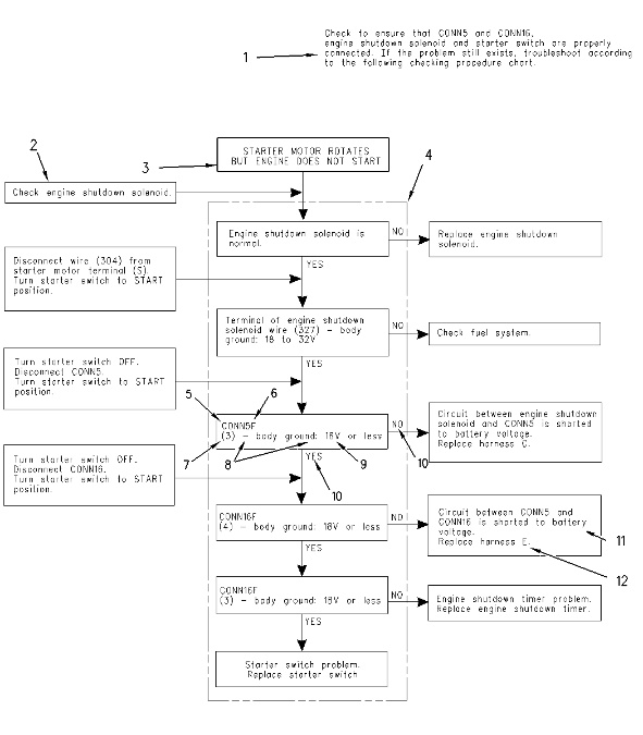
- The connections (1) are listed in a paragraph above the diagram. Check the listed connections (1) before troubleshooting. Check for water that has accumulated in connectors. Check that the pins are not loose.
- Preparations (2) provide the preliminary arrangements that must be made before troubleshooting.
- Problem statement (3) is the problem in the electrical system. The troubleshooting procedure attempts to solve the problem that is described in the statement.
- Test steps (4) must be followed in sequence until a solution (corrective action) is determined. The tests must be performed with a digital multimeter.
- Connect the multimeter leads across measuring points (8). A dash follows the first measuring point, and a colon follows the second measuring point. For example, if the procedure shows “CONN5F (3) – body ground:”, connect the leads across socket 3 (female end) of connector 5 and body ground (frame ground). If there are multiple measuring points in one connector, then the connector number may be listed once in the test step. For example, “CONN5F (1) – (2):” is equivalent to “CONN5F (1) – CONN5F (2):”.
- Connector number (5) is found on the Electrical System Schematic and on the connector location chart.
- Gender of the connector (6) is either male “M” (pin) or female “F” (socket).
- Pin number (7) for the connector is found on the Electrical System Schematic.
- Expected result (9) can be a voltage, a resistance, or another quantity. The expected result follows the colon in the test step. If actual result (10) matches the expected result, follow the “YES” arrow. Otherwise, follow the “NO” arrow.
- Cause (11) will list the probable cause(s) of a problem.
- Solution (12) shows the corrective action that should be taken to solve a particular problem.
- When you are instructed to replace an item, attempt to repair the item first.
- When a continuity check is performed, turn the start switch to the OFF position. This action will stop the power supply in order to prevent damage to the tester or to the power supply.
- When a voltage check is performed in the starting circuit, turn the start switch to the ON position. The engine should be in operation. Stable inputs and stable outputs of the engine controller cannot be obtained without the engine in operation.
- When “0 ohms” appears in the procedures, the electrical circuit has continuity. When “infinite ohms” or “inf. ohms” appears in the procedures, the electrical circuit does not have continuity.
|
|
| NOTICE |
|---|
|
To avoid damage to electrical components when the power supply is on, make sure that the disconnected connectors and wires do not come in contact with the machine. |
|
|