| Component Identification (CID) | ||
| CID No. | Name Of Component | |
| 91 (Not in 321C) |
Throttle position signal | |
| 96 | Fuel level sensor | |
| 110 | Engine coolant temperature sensor | |
| 167 | Alternator | |
| 168 | Voltage to the power supply (keyswitch) | |
| 190 | Speed sensor | |
| 248 ( 319C, 320C, 322C, 325C, and 330C ONLY) |
Cat Data Link | |
| 254 ( 312C, 315C, and 321C ONLY) |
Electronic Control Module (ECM) | |
| 271 ( 312C, 315C, and 321C ONLY) |
Action Alarm | |
| 286 (Not in 321C) |
Engine oil pressure fault | |
| 374 | Swing brake solenoid | |
| 376 | Travel alarm | |
| 581 | Proportional reducing valve for the power shift pressure | |
| 586 | Engine speed dial | |
| 587 | Feedback of the governor actuator | |
| 588 ( 312C, 315C, and 321C ONLY) |
Communication problem between controller and monitor | |
| 590 | Engine controller | |
| 598 | Automatic travel speed solenoid | |
| 600 | Hydraulic oil temperature sensor | |
| 1161 | Pressure sensor for the delivery pump (1) | |
| 1162 | Pressure sensor for the delivery pump (2) | |
| 1525 | Straight travel solenoid | |
| 2002 ( 319C, 320C, 322C, 325C, and 330C ONLY) |
Travel alarm | |
|
|
|
|
|
|
| Illustration 1 | g00691520 |
|
Example Of A Typical Troubleshooting Procedure (1) Preparations (2) Description of the problem (3) Error code on the display (4) Items that require checking (5) Probable cause and solution |
|
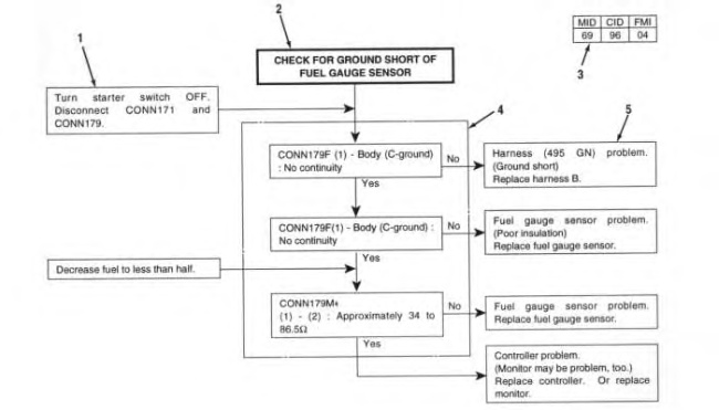
- Description (Items that require checking)
|
|
|
|
|
|
| Illustration 2 | g00987164 |
|
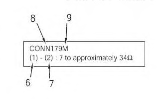
Diagram Of Terminology For The Troubleshooting Procedures (6) Number of the terminal in the connector (7) Indication of the short circuit (8) Number of the connector (9) “M” Male “F” Female |
|
- Measurement of Voltage
- (A) – (B) : 24 V
Voltage is measured at the later terminal. For example, the red test pin + is connected to terminal “A” and the black test pin – is connected to terminal “B”.
- Meaning of Symbols
- The following list describes the meaning of specific symbols:
- “C-ground” : Ground terminal for the chassis
- “P-ground” : Ground terminal for the platform
- “R-ground” : Ground terminal for the relay panel
- “Cab-ground” : Ground terminal for the cab
- The following list describes the meaning of specific symbols:
- Preliminary Check
- Connector
Check the connection of the connector before a troubleshooting procedure is performed. Inspect the connector for moisture. Moisture in a connector can cause a poor connection. Ensure that the connectors are mating correctly. Ensure that the pins in the connector are secure.
- Continuity
Ensure that continuity is present between the following items:
- “C-ground” – “P-ground”
- “C-ground” – “R-ground”
- “P-ground” – “Cab-ground”
Turn the disconnect switch to the OFF position before you perform the continuity checks. The power is OFF in order to prevent damage to the tester and the circuit.
- Connector
- Preparation
- Turn the key start switch to the OFF position.
- The hydraulic control lever is in the LOCKED position.
- Ensure that the controller, the harnesses and the connectors are connected.
Note: Ensure that disconnected wires do not contact the machine in order to avoid damage to electrical components when power is applied.