|
|
|
|
|
|
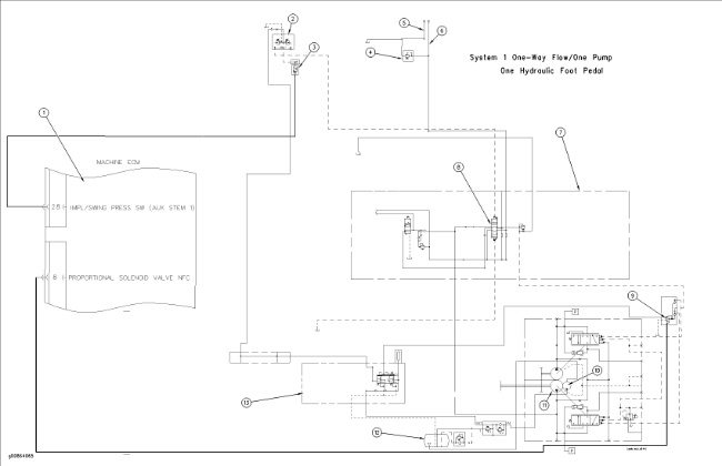
| Illustration 1 | g00864065 |
|
(1) Machine electronic control module (2) Foot pedal (3) Work tool pressure switch (4) Line relief valve (5) Line for work tool (6) Line for work tool (7) Main control valve (8) Attachment control valve (9) Proportional reducing solenoid valve (10) Pilot pump (11) Drive pump (12) Hydraulic tank (13) Pilot manifold |
|
The default parameter values for System 1 are for one-way hydraulic oil flow from one main pump. Refer to Testing and Adjusting, “System 1: Default Value of Work Tool Parameters” for the Tool Control System.
Use the display monitor or ET in order to set the hydraulic flow to the work tool.
The work tool is operated by one hydraulic foot pedal that is located in the cab.
|
|
|
|
|
|
| Illustration 2 | g00606536 |
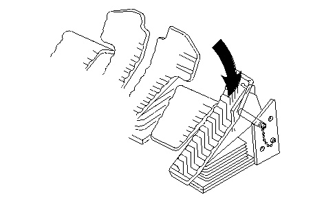
Pilot pump (10) supplies oil to pilot manifold (13) . When the hydraulic activation lever is moved to the UNLOCK position, pilot oil flows from pilot manifold (13) to foot pedal (2) . When right foot pedal (2) is depressed FORWARD, pilot oil flows to attachment control valve (8) . The pilot oil will shift the spool in the valve to the DOWNWARD position. This allows oil from drive pump (11) to flow through attachment control valve (8) . The pump oil flows through the line for the work tool (6) to the work tool. The pump oil flows to relief valve (4) . The working pressure for the work tool is controlled by relief valve (4) . Return oil flows through the line for the work tool (5) and back to hydraulic tank (12) .
During the operation of the work tool, work tool pressure switch (3) senses pilot pressure.
Work tool pressure switch (3) signals the machine electronic control module. The machine ECM sends a signal to the proportional solenoid valve for negative flow control (9) . Negative flow control pressure in the center bypass passage is blocked when the valve spools shift DOWNWARD. The machine ECM has programmed parameter values “101”, “102”, and “103” for flow and pressure for the work tool. The machine ECM calculates the minimum negative flow control pressure that will be supplied to the pump regulator. When the work tool is activated, proportional solenoid valve (9) receives a signal from the machine ECM. The signal is a result of the calculation. The negative flow control pressure forces the swashplate in the pump to the correct angle to limit the flow and pressure.
The pressure setting for the relief valve must be reset to the specification of the supplier for the work tool that is being used.