|
|
|
|
|
|
| Illustration 1 | g02797497 |
|
Swing motor (1) Relief valve (2) Relief valve (3) Motor head (4) Port (pilot system oil) (5) Separator plate (6) Friction plate (7) Plate (8) Body (9) Drive shaft (10) Check valve (11) Makeup port (12) Drain port (13) Passage (supply oil or return oil) (14) Check valve (15) Passage (supply oil or return oil) (16) Port (supply oil or return oil) (17) Port (supply oil or return oil) (18) Passage (supply oil or return oil) (19) Valve plate (20) Passage (supply oil or return oil) (21) Brake spring (22) Brake piston (23) Piston (24) Cylinder barrel (25) Retainer plate (26) Shoe |
|
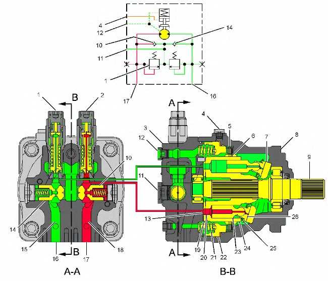
The swing motor may be divided into the following three groups:
- The rotary group consists of the following components: cylinder barrel (24), pistons (23), shoes (26), retainer plate (25) and drive shaft (9) .
- The parking brake consists of the following components: brake spring (21), brake piston (22), separator plate (5) and friction plate (6) .
- The relief valves and the makeup valves consist of the following components: relief valve (1), relief valve (2), check valve (10) and check valve (14) .
Supply oil from the pump is delivered to port (16) or port (17). During a SWING RIGHT operation, the oil delivery enters motor head (3) at port (17) and flows through passage (18). The oil then flows through passage (13) in valve plate (19) and passes through passage (20) in cylinder barrel (24). This oil pressurizes piston (23) in motor head (3).
|
|
|
|
|
|
| Illustration 2 | g01335656 |
|
Motor passages (A) Bottom center position (B) Inlet side (high pressure) (C) Top center position (D) Outlet side (low pressure) (13) Passage (valve plate) (15) Return passage (16) Port (17) Port (18) Supply passage (20) Passage (cylinder barrel) (27) Passage (valve plate) (28) Direction of motor rotation (counterclockwise rotation) |
|
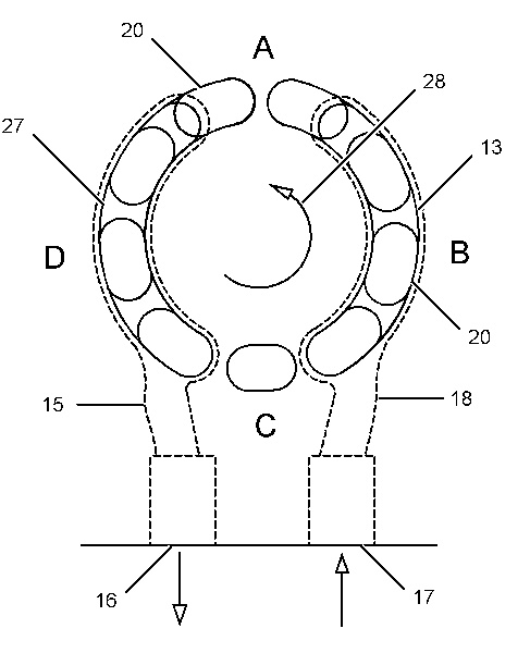
Shoe (26) is pressed against the upper surface of plate (7) by the force of piston (23). The shoe and the piston slide along the slope of plate (7) in a counterclockwise direction. This sliding force causes cylinder barrel (24) to rotate in a counterclockwise direction (28). As each piston reaches the bottom center position (A), oil flows through passage (27) in valve plate (19). This oil then flows through passage (15) of motor head (3) to the hydraulic tank. As cylinder barrel (27) continues to rotate counterclockwise, the piston and the shoe continue to move up the inclined surface of plate (28). Since cylinder barrel (24) is splined to drive shaft (9), the drive shaft rotates in the same direction as the cylinder barrel.
For a SWING LEFT operation, swing pump supply oil is delivered to port (16). The supply ports and the return ports are reversed. Cylinder barrel (24) turns clockwise.
The case drain oil from the swing motors returns through drain port (12) of motor head (3) to the hydraulic tank.
ReferenceFor more information concerning the swing parking brake, refer to Systems Operation, “Pilot Valve (Swing Parking Brake)”.
ReferenceFor more information concerning the swing relief valves, refer to Systems Operation, “Relief Valve (Swing)”.