"C" SERIES SKID STEER LOADERS Service Training Meeting Guide Page 1
Service Training Meeting Guide
Contents Summary of "C" SERIES SKID STEER LOADERS Service Training Meeting Guide
- Page 1SERV1833-01 July 2008 GLOBAL SERVICE LEARNING TECHNICAL PRESENTATION "C" SERIES SKID STEER LOADERS 246C/256C/262C/272C MULTI TERRAIN LOADERS 277C/287C/297C COMPACT TRACK LOADERS 279C/289C/299C Service Training Meeting Guide (STMG)�
- Page 2"C" SERIES SKID STEER LOADERS 246C/256C/262C/272C MULTI TERRAIN LOADERS 277C/287C/297C COMPACT TRACK LOADERS 279C/289C/299C AUDIENCE Level II - Service personnel who understand the principles of machine system operation, diagnostic equipment, and procedures for testing and adjusting. CONTENT This pr
- Page 3SERV1833-01 -3- Text Reference 07/08 TABLE OF CONTENTS INTRODUCTION ........................................................................................................................5 Similarities and Differences .................................................................................
- Page 4SERV1833-01 -4- Text Reference 07/08 NOTES Changes made to Visuals, 2, 11, 12, and 53. Text changes made to pages, 5, 7, 15, 26, 28, 29, 36, 37, 39, 53, 62, and 63 July 08 changes: Text changes made to pages, 1 thru 9, 14 - 15, 30,- 31, 41, 53 - 55, 80 - 86, 92. Visuals: 31, 58, 74 thru 76 thru 79�
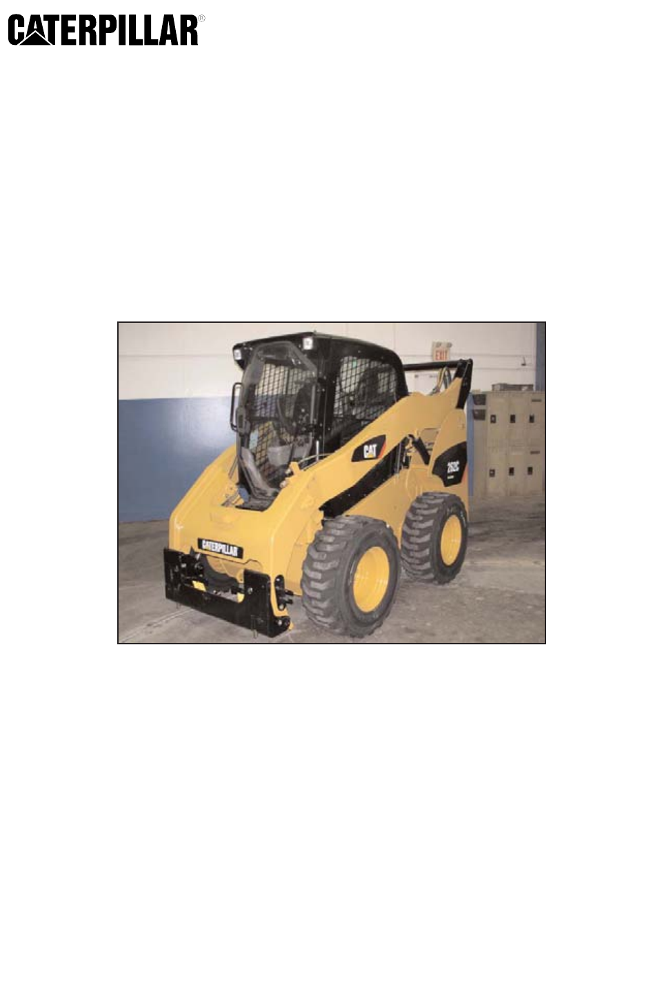
- Page 5SERV1833-01 -5- Text Reference 07/08 "C" Series SKID STEER LOADERS 246C/256C/262C/272C MULTI TERRAIN LOADERS 277C/287C/297C COMPACT TRACK LOADERS 279C/289C/299C © 2008 Caterpillar 1 INTRODUCTION The 246C/256C/262C/272C Skid Steer Loaders, the 277C/287C/297C Multi Terrain Loaders and the 279C/289C/29
- Page 6SERV1833-01 -6- Text Reference 07/08 KEY NEW FEATURES - Operator's Station - Electronically Controlled Hydrostatic Drive System - Electronically Controlled Work Tool Hydraulic System - Improved Electrical System - Ride Control System (SSL only) - High Flow Hydraulic XPS System Optional on all Machin
- Page 7SERV1833-01 -7- Text Reference 07/08 Ride Control has been added as an option on the Skid Steer Loaders only. The Ride Control System operates similarly to current Caterpillar wheel loaders. The optional high flow XPS hydraulic system is now optional on all "C" Series machines. A creeper control fun
- Page 8SERV1833-01 -8- Text Reference 07/08 SIMILARITIES AND DIFFERENCES FEATURES DIFFERENT SIMILAR SAME Machine Appearance X Operator's Station X Engine X Electrical X Hydrostatic Drive System X Work Tool Hydraulic System X Undercarriage X Maintenance Items X 3 Similarities and Differences The chart above
- Page 9SERV1833-01 -9- Text Reference 07/08 4 OPERATOR'S STATION The new Skid Steer Loader cab provides optimal space. Machines equipped with the optional enclosed cab (as shown in this illustration), a new door provides the operator with greater visibility to the work tool. The new cab is sealed and has a
- Page 10SERV1833-01 - 10 - Text Reference 07/08 5 The cab can be raised by removing two bolts at the front of the cab, which allows easy access to components. The bolt (arrow) on the right side of the machine is shown in this illustration. The cab rotates up as a complete unit.�
- Page 11SERV1833-01 - 11 - Text Reference 07/08 3 2 5 5 3 1 6 4 6 The top illustrations show the air conditioning ducting. Air flows into the machine through the fresh air inlet (1). Air flows into the evaporator compartment (2) through a duct (3) below the cab. The air passes over the evaporator (4) and is
- Page 12SERV1833-01 - 12 - Text Reference 07/08 1 3 2 7 This cab is equipped with a mechanical suspension seat. There are two armrests (1) in the "C" Series machines, which rotate from side-to-side. In this illustration the armrests are shown in the UP position. The seat can be moved back and forth with the
- Page 13SERV1833-01 - 13 - Text Reference 07/08 1 3 2 8 In this illustration the armrests (1) are shown in the DOWN position. This cab is equipped with an optional air suspension seat. The seat can be moved back and forth with the seat lever (2) below the left side of the seat. The knob (3) located below th
- Page 14SERV1833-01 - 14 - Text Reference 07/08 3 2 6 4 5 1 9 The left and right joysticks are adjustable fore / aft independently from the seat. The joystick adjustment lever (1) is located to the rear of the joystick. Additionally the joystick pods are seat mounted, which provides for greater controllabil
- Page 15SERV1833-01 - 15 - Text Reference 07/08 4 3 5 2 1 10 The right joystick adjustment lever (1) is located to the rear of the joystick. In the standard control lever pattern, the right joystick (2) provides work tool control and functions the same as previous models. The thumb switch (3) controls the p
- Page 16SERV1833-01 - 16 - Text Reference 07/08 AUXILIARY FUNCTIONS STANDARD CONFIGURATION C1 C2 C D E A2 B A H G F Work Tool Electrical Connector Electrical Pin Arrangement A1 Connector Auxiliary Hydraulic Connections C1 Aux 6 Thumb Switch (A1/A2 Aux) C2 Aux 5 Left Joystick Right Joystick 11 This illustrat
- Page 17SERV1833-01 - 17 - Text Reference 07/08 Work Tool Electrical Connector Return AUXILIARY FUNCTIONS HIGH FLOW CONFIGURATION C+ C- High Flow High Flow (A2) C1 C2 (A1) Standard Standard (A2) C D E (A1) Aux 7 B A H G F Electrical Connector Pin Arrangement Auxiliary Hydraulic Connections C+ Aux 4 C1 Aux 6
- Page 18SERV1833-01 - 18 - Text Reference 07/08 CONTROL LEVER PATTERNS Standard Bucket Foward Lower Left Right Tilt Tilt Turn Turn Backward Forward Reverse Bucket Raise Optional LH Forward RH Forward Bucket Bucket Tilt Tilt Raise Lower Backward Forward LH Reverse RH Reverse 13 Two control patterns are avail
- Page 19SERV1833-01 - 19 - Text Reference 07/08 1 2 3 4 5 8 9 7 6 10 14 The fuse panel (1), the document compartment (2), the recirculation filter (3), and the radio (4) are all located at the rear of the cab. NOTE: All machines are equipped with radio wiring and a radio mounting location. However, the radi
- Page 20SERV1833-01 - 20 - Text Reference 07/08 15 The cab fresh air filter is located on the left side at the rear of cab. Remove the filter cover (arrow) to service the filter element.�
- Page 21SERV1833-01 - 21 - Text Reference 07/08 16 Lifting hooks (arrows) can be attached to optional mounts on the top of the cab for lifting the machine. A four-point lifting kit is optional.�
- Page 22SERV1833-01 - 22 - Text Reference 07/08 17 1 2 18 The governor control lever (1) is shown in the top illustration and the accelerator pedal (2) is shown in the bottom illustration. A new throttle position sensor (not shown) is located on the accelerator pedal assembly.�
- Page 23SERV1833-01 - 23 - Text Reference 07/08 2 1 19 The throttle position sensor (1) is located at the base of the accelerator pedal assembly (2). The throttle position sensor sends a signal to the Machine ECM indicating the accelerator pedal position. The throttle position signal is used by the Machine
- Page 24SERV1833-01 - 24 - Text Reference 07/08 20 This illustration shows the relocated windshield washer reservoir (arrow).�
- Page 25SERV1833-01 - 25 - Text Reference 07/08 21 A dead engine lower handle (arrow) has been installed in the cab to allow the lift arms to be lowered from inside the cab in the event of a dead engine and no electrical power or in the event of an uncharged accumulator.�
- Page 26SERV1833-01 - 26 - Text Reference 07/08 22 1 2 5 6 23 3 4 In a situation where the operator is unable to lower the lift arms, there is an unlocking mechanism built into the door. To remove the door, the top handle (2) must be pulled up and the bottom handle (3) pulled down. Then, the gas strut (1) m
- Page 27SERV1833-01 - 27 - Text Reference 07/08 1 2 3 4 5 6 7 8 24 The left overhead console includes the following switches: -Auxiliary hydraulic pressure release (1) -Hydraulic lockout and interlock override (2) -Rear work lights (3) -Front work lights (4) -Auxiliary 7/two-speed selection switch (5) -Auxi
- Page 28SERV1833-01 - 28 - Text Reference 07/08 9 10 7 8 4 25 3 2 1 10 8 5 26 6 4 The left overhead display includes the key start switch (1), the 12-volt receptacle (2), the parking brake switch (3), and the joystick control pattern switch (4, if equipped). If the pattern switch is installed, either the st
- Page 29SERV1833-01 - 29 - Text Reference 07/08 27 1 2 3 4 28 5 The heating and air conditioning controls have been moved to the right overhead console. The switches include the fan speed control switch (1), the air conditioning control switch (2), and the temperature control switch (3). To the left of the
- Page 30SERV1833-01 - 30 - Text Reference 07/08 2 3 1 5 4 29 6 7 8 30 4 The optional Advanced Machine Information and Control System (AMICS) display panel includes a digital display panel (1) with a coolant temperature gauge (2) and a hydraulic oil temperature gauge (3). A digital display window (4) is used
- Page 31SERV1833-01 - 31 - Text Reference 07/08 2 1 3 31 The optional Advanced Machine Information and Control System (AMICS) display panel will show various machine information in three Operator Modes and eight Service Modes. The function selector key (1) is used to toggle between available modes. The scro
- Page 32SERV1833-01 - 32 - Text Reference 07/08 32 2 1 33 2 1 These illustrations show the display panel in the Service Mode. To display the Service Mode press and hold the function select key (1) and the scroll up key (2) for at least three seconds. The function select key allows navigation between modes a
- Page 33SERV1833-01 - 33 - Text Reference 07/08 - Mode 3 (Logged Events): displays the logged event codes. - Mode 4 (Software P/N Machine): displays the currently installed Machine ECM software part number. - Mode 5 (Machine Parameters): displays the engine coolant temperature, the hydraulic oil temperature
- Page 34SERV1833-01 - 34 - Text Reference 07/08 5 6 7 3 1 2 8 9 4 5 6 9 8 4 4 11 10 34 ENGINE The 3044C engine is similar to the "B" Series machines. The engine ratings have been increased and an ATAAC has been added to the 272C and 297C machines to increase power. The bottom views show the front of the eng
- Page 35SERV1833-01 - 35 - Text Reference 07/08 - Fuel tank and filler cap (8) - Engine oil dipstick (9) - Air conditioning compressor (10): The compressor has been moved into the engine compartment and is now driven by a belt. - Engine oil filter (11)�
- Page 36SERV1833-01 - 36 - Text Reference 07/08 1 2 35 The oil filter (1) is now mounted vertically for improved serviceability. The "C" Series engine is equipped with an open breather system(2).�
- Page 37SERV1833-01 - 37 - Text Reference 07/08 2 3 36 4 1 37 An Air to air aftercooler (ATAAC) (1) has been added to the 272C Skid Steer Loader and the 297C Multi-Terrain Loader. The ATAAC housing (2) and hydraulic drive motor (3) for the ATAAC fan are located at the back of the engine compartment behind t
- Page 38SERV1833-01 - 38 - Text Reference 07/08 38 In cold weather, the glow plugs are powered by the Machine ECM through the cold start relay when the key start switch is turned to the ON position. The glow plug indicator (arrow) on the left overhead console will illuminate when the key start switch is tur
- Page 39SERV1833-01 - 39 - Text Reference 07/08 39 ELECTRICAL SYSTEM The battery (arrowed) has been relocated under the cab from the engine compartment. A remote jump start receptacle is located in the engine compartment as previously described.�
- Page 40SERV1833-01 - 40 - Text Reference 07/08 1 3 2 2 40 The single Machine ECM (1) is located at the back of the cab. Two power relay modules (2) and six fuses (not visible) are also located behind the cab. The fuses are accessed by removing the fuse covers (3). The Machine ECM is an A4:M1 ECM with two 7
- Page 41SERV1833-01 - 41 - Text Reference 07/08 MACHINE ECM INPUTS AND OUTPUTS Key Start Switch Two Speed Solenoid Engine Speed Sensor Engine Coolant Temperature Sensor Left Hystat Pump Forward Solenoid Hydraulic Oil Temperature Sensor Left Hystat Pump Reverse Solenoid Fuel Level Sensor Right Hystat Pump Fo
- Page 42SERV1833-01 - 42 - Text Reference 07/08 The Machine ECM controls the following work tool hydraulic system features: -Auxiliary bleed off control -Auxiliary tool control -Bucket tilt control -Lift arm raise/lower control -Continuous flow control -Interlock override control -Joystick pattern changer -
- Page 43SERV1833-01 - 43 - Text Reference 07/08 42 Cat ET can be used for configuring and diagnosing the "C" Series machines. This screen shows the Machine status screen. Several status screen are available to aid in troubleshooting Machine ECM controlled functions. The screens are: - Machine - Interlock -
- Page 44SERV1833-01 - 44 - Text Reference 07/08 43 This illustration shows the machine Configuration screen. Several "C" Series machine features can be installed using the Configuration screen.�
- Page 45SERV1833-01 - 45 - Text Reference 07/08 44 The following components can be calibrated using Cat ET: - Throttle position sensor - Joystick control levers - Work tool hydraulic system solenoids - Hystat pump solenoids - Demand fan solenoid�
- Page 46SERV1833-01 - 46 - Text Reference 07/08 45 The Machine ECM, left console display, and right console display can all be flashed using the Cat ET WinFlash program.�
- Page 47SERV1833-01 - 47 - Text Reference 07/08 MACHINE ECM INPUTS AND OUTPUTS Key Start Switch Two Speed Solenoid Engine Speed Sensor Left Hystat Pump Forward Solenoid Engine Coolant Temperature Sensor Left Hystat Pump Reverse Solenoid Hydraulic Oil Temperature Sensor Right Hystat Pump Forward Solenoid Fue
- Page 48SERV1833-01 - 48 - Text Reference 07/08 The Machine ECM determines operator requests from input signals from the key start switch, the park brake switch, and the hydraulic lockout switch. The Machine ECM controls engagement of the starter motor. The start relay is powered by the Machine ECM when the
- Page 49SERV1833-01 - 49 - Text Reference 07/08 HYDROSTATIC DRIVE SYSTEM Left Motor Right Motor Speed Sensor Speed Sensor Left Right Motor Motor Engine Speed Sensor Throttle Lever Position Sensor Parking Parking Machine Brake Brake ECM Joystick Position Signals Park Brake Switch Pump Control Pump Control Cr
- Page 50SERV1833-01 - 50 - Text Reference 07/08 1 3 8 6 4 2 11 7 12 9 5 10 48 This illustration shows the right side of the hydrostatic pump. From this side of the pump the following components are visible: - Left motor reverse pump solenoid (1) - Left motor servo pressure port (2) - Right motor servo press
- Page 51SERV1833-01 - 51 - Text Reference 07/08 3 5 6 2 4 1 7 8 15 9 10 14 13 11 12 49 This illustration shows the left side of the hydrostatic pump. From this side of the pump the following components are visible: - Right forward pump solenoid (1) - Right forward drive loop port (MC) (2) - Brake supply por
- Page 52SERV1833-01 - 52 - Text Reference 07/08 - Charge oil inlet port (10) - Left forward travel drive loop port (11) - Left reverse travel drive loop port (12) - Right reverse travel drive loop port (13) - Right forward travel drive loop port (14) - Case drain port (15)�
- Page 53SERV1833-01 - 53 - Text Reference 07/08 1 50 The SSL travel drive motors are radial piston motors with a similar type of design as the "B" Series machines. The brakes are spring engaged and hydraulically released. The MTL drive motors are axial piston motors Each hydrostatic drive motor contains a f
- Page 54SERV1833-01 - 54 - Text Reference 07/08 HYDROSTATIC DRIVE SYSTEM PARK BRAKE APPLIED To Pilot Shutoff From Manual Solenoid Lowering Valve From Pilot Shutoff Cooler Solenoid From Work Tool To / From Valve Group Travel Motor Travel Motor Work Tool Flushing Flushing Coupler Valve Return Hydraulic System
- Page 55SERV1833-01 - 55 - Text Reference 07/08 In HOLD, the speed and direction control lever is centered. No signal is sent from the control lever to the Machine ECM. The pump control valves are held in the center position by spring force and no pressure oil is directed to the actuator pistons. With no si
- Page 56SERV1833-01 - 56 - Text Reference 07/08 HYDROSTATIC DRIVE SYSTEM FORWARD To Pilot Shutoff From Manual Solenoid Lowering Valve From Pilot Shutoff Cooler Solenoid From Work Tool To / From Valve Group Travel Motor Travel Motor Work Tool Flushing Flushing Coupler Valve Return Hydraulic System Valve Valv
- Page 57SERV1833-01 - 57 - Text Reference 07/08 The signal pressure oil at the actuator pistons moves the swashplates to the forward position. As the swashplates move, pump output flow increases and is sent to the drive motors. The oil from the pump also flows to the top of the flushing valve and moves it d
- Page 58SERV1833-01 - 58 - Text Reference 07/08 TWO-SPEED SSL HYDROSTATIC DRIVE SYSTEM RABBIT MODE / FORWARD Two-speed Valve To Drain Manifold To Pilot Shutoff Solenoid Travel Motor Flushing Flushing Two-speed Valve Two-speed Valve Selector Spool Selector Spool Park Brake Travel Motor Park Brake Left Pump S
- Page 59SERV1833-01 - 59 - Text Reference 07/08 TWO-SPEED MTL HYDROSTATIC DRIVE SYSTEM RABBIT MODE / FORWARD To Pilot To Drain Manifold Shutoff Solenoid Two-speed Valve Travel Motor Parking Parking Brake Brake Flashing Valve Final Final Drive Drive Two-speed Selector Spool Left Pump Solenoid Valve Right Pum
- Page 60SERV1833-01 - 60 - Text Reference 07/08 ELECTRONIC CONTROL SYSTEM ENGINE UNDERSPEED FUNCTION Left Forward Engine Speed Pump Solenoid Left Reverse Sensor Pump Solenoid Throttle Position Machine ECM Right Forward Right Reverse Sensor Pump Solenoid Pump Solenoid 54 This illustration shows the component
- Page 61SERV1833-01 - 61 - Text Reference 07/08 When a travel mode is selected and the engine speed is increased, the Machine ECM increases the signal to the pump control solenoid valves. This action results in higher speed once the speed and direction lever is moved. When the machine decelerates, the trave
- Page 62SERV1833-01 - 62 - Text Reference 07/08 9 3 2 7 4 56 10 1 5 6 5 1 8 4 7 10 10 57 5 5 6 Two types of undercarriages are available on the "C" Series Multi-Terrain Loaders. The top illustration shows the Dual Level Suspension (DLS). The bottom illustration shows the Single Level Suspension (SLS). The D
- Page 63SERV1833-01 - 63 - Text Reference 07/08 The hydrostatic motor requires an oil change after the first 250 service hours and every subsequent 500 service hours. The roller frame assembly (4) supports the front and rear idler wheels (5) and the bogie wheels (6). The tensioner (7) allows adjustment of t
- Page 64SERV1833-01 - 64 - Text Reference 07/08 1 4 2 3 58 The fan (1) and fan motor (2) are located in the rear compartment. The fan provides cooling air for the radiator and hydraulic oil cooler. The fan motor receives oil flow from the charge pump to drive the fan. The "C" Series machines are equipped wi
- Page 65SERV1833-01 - 65 - Text Reference 07/08 DEMAND FAN CIRCUIT To Work MAXIMUM FAN SPEED Tool Coupler S O S Tap To Hydrostatic Demand Drive Pump Fan Motor Charge Hydraulic Oil Pump Machine Temperature Sensor ECM Coolant Temperature Sensor Demand Fan Solenoid Valve 59 Oil from the charge pump flows to th
- Page 66SERV1833-01 - 66 - Text Reference 07/08 WORK TOOL HYDRAULIC SYSTEM Diverter Valve Ride Work Tool Control Lift Tilt Auxiliary Control Valve Lift Pilot Aux Pilot Solenoids Tilt Pilot Solenoids Solenoids Pilot Supply Solenoid Continuous Flow Switch Auxiliary Hydraulic Pressure Release Switch Machine Hy
- Page 67SERV1833-01 - 67 - Text Reference 07/08 1 61 2 62 The hydraulic tank includes a new breather (1) at the top of tank that is serviceable. The tank will have a hydraulic oil level sight glass (2) on the side of tank that is more visible from the right side of the machine.�
- Page 68SERV1833-01 - 68 - Text Reference 07/08 4 1 2 3 63 The radiator (1) and hydraulic oil cooler (2) are more accessible in the "C" Series machines because the grill raises to a higher angle than the "B" Series machines. An oil fill access (3) has been added to the oil cooler to allow hydraulic oil to b
- Page 69SERV1833-01 - 69 - Text Reference 07/08 1 3 2 64 4 65 5 The top illustration shows the standard work tool gear pump (1) for a machine without the High Flow option. Also shown is the ATAAC pump (2) mounted to the charge pump (3). The bottom illustration shows the variable displacement piston pump (4)
- Page 70SERV1833-01 - 70 - Text Reference 07/08 1 2 66 1 2 67 The work tool control valve (1) and diverter (self-leveling) valve (2) are located above the right frame rail. The self-leveling option has the same functionality as the "B" Series machines. A removable panel (not visible) allows easy access to t
- Page 71SERV1833-01 - 71 - Text Reference 07/08 12 1 1 2 13 2 4 3 5 3 6 7 4 8 8 5 9 9 6 10 10 7 11 13 11 14 14 68 These illustrations show the work tool control valve on a High Flow machine in different positions. The top left illustration shows the work tool control valve in the same position as it would b
- Page 72SERV1833-01 - 72 - Text Reference 07/08 2 1 69 4 3 70 Travel at high speeds over rough terrain causes work tool movement. The optional Ride Control System acts as a shock absorber by absorbing work tool forces, which stabilize the machine. The new ride control valve (1) is located next to the divert
- Page 73SERV1833-01 - 73 - Text Reference 07/08 RIDE CONTROL SYSTEM ON Lift Cylinders Ride Control Valve To / From Ride Control Work Tool Accumulator Lift Valve Accumulator Ride Precharge Valve Machine Control Ride Control Switch ECM Relay From Charge Pump 71 This illustration shows a hydraulic schematic of
- Page 74SERV1833-01 - 74 - Text Reference 07/08 1 72 3 1 73 2 The implement pilot shutoff valve (1) is located on the right frame rail to the rear of the right travel motor. The pilot shutoff solenoid (2) blocks oil to the work tool control valve solenoids when the hydraulic lockout switch in the cab is act
- Page 75SERV1833-01 - 75 - Text Reference 07/08 74 Cat ToughGuard™ hydraulic hoses are used on the "C" Series machines. ToughGuard™ hoses provide abrasion resistance, which exceeds the capabilities of standard hydraulic hoses. The ToughGuard™ hoses include a polyethylene exterior cover, which eliminates the
- Page 76SERV1833-01 - 76 - Text Reference 07/08 WORK TOOL HYDRAULIC SYSTEM HOLD Lift Tilt Auxiliary Cylinders Cylinders Tools Line Relief Valves Line Relief Line Relief Valve Valve Work Tool Valve Group Raise Dump Aux Solenoid Solenoid Solenoid Valve Valve Valve Ride Control Diverter Valve Valve Main Relief
- Page 77SERV1833-01 - 77 - Text Reference 07/08 The optional automatic level control uses a diverter valve to maintain the work tool in a level position during the raising of the loader arms. At machine start-up with the work tool control lever in HOLD, the charge pump sends oil through the fan motor and th
- Page 78SERV1833-01 - 78 - Text Reference 07/08 WORK TOOL HYDRAULIC SYSTEM RAISE Lift Tilt Auxiliary Cylinders Cylinders Tools Line Relief Valves Line Relief Line Relief Valve Valve Work Tool Valve Group Raise Dump Aux Solenoid Solenoid Solenoid Valve Valve Valve Ride Control Diverter Valve Valve Main Relie
- Page 79SERV1833-01 - 79 - Text Reference 07/08 If the work tool control lever is only partially shifted, some pump supply oil is metered through the center of the lift valve to the next circuit and then to the tank (unless one of the other control valves is fully shifted). If the lift circuit is stalled in
- Page 80SERV1833-01 - 80 - Text Reference 07/08 OPTIONAL HIGH FLOW XPS HYDRAULIC SYSTEM HOLD Tilt Cylinders Work Auxiliary Tool Lift Tools Cylinders Line Relief Valves Auxiliary Solenoid Valve A2 C+ Solenoid Valve Raise Solenoid Dump Load Sensing Aux Pump Valve Solenoid Signal Rail Rail Valve Ride Divert er
- Page 81SERV1833-01 - 81 - Text Reference 07/08 The operation of the valve is identical to that of the B Series valve, however the high flow selector switch has been removed. The High Flow operation is now contolled by the presence of a High Flow enabled worktool being detected across pins F and G on the wo
- Page 82SERV1833-01 - 82 - Text Reference 07/08 78 Compact Track Loader Update The CTL range consists of three machines, the the 279C, 289C and the 299C. These machines are built on the current MTL chassis and Tier 3 engine configurations, but are equipped with a CAT designed and manufactured suspended CTL
- Page 83SERV1833-01 - 83 - Text Reference 07/08 3 1 6 2 4 7 5 79 The undercarriage design comprises of the following main components: - Frame assembly (1) - Recoil / grease tensioner and front idler assembly (2) - Drive motor and planetary final drive (3) - Rear idler (4) - Roller wheels (5) - Torsion axles
- Page 84SERV1833-01 - 84 - Text Reference 07/08 80 Tier 3 UPDATE From February 2008, the 3044C DIT Tier 2 engine was replaced by the C3.4 Turbochaged Tier 3 engine, with the horsepower ratings for each machine remaining the same as Tier 2. The C3.4 Tier 3 engine has been redesigned to include the following
- Page 85SERV1833-01 - 85 - Text Reference 07/08 81 CONCLUSION This presentation has provided information on the "C" Series Skid Steer Loaders, Multi Terrain Loaders and Compact Terrain Loaders. Key service features, new components, and component locations were identified and discussed. This presentation sup
- Page 86SERV1833-01 - 86 - Visual List 07/08 VISUAL LIST 1. Model view 43. Machine configuration screen 2. Key new features 44. Component calibration using ET 3. Similarities and differences 45. Cat ET Winflash program 4. Operator's station 46. Machine ECM inputs and outputs - 5. Right side of cab interlock
- Page 87SERV1833-01 - 87 - Text Reference 07/08 HYDRAULIC SCHEMATIC COLOR CODE Black - Mechanical connection. Seal Red - High pressure oil Dark Gray - Cutaway section Red/White Stripes - 1st pressure reduction Light Gray - Surface color Red Crosshatch - 2nd reduction in pressure White - Atmosphere or Pink -
- Page 88SERV1833-01 HYDRAULIC SCHEMATIC COLOR CODE 07/08 Black - Mechanical connection. Seal Red - High pressure oil Dark Gray - Cutaway section Red/White Stripes - 1st pressure reduction Light Gray - Surface color Red Crosshatch - 2nd reduction in pressure White - Atmosphere or Pink - 3rd reduction in pres
- Page 89SERV1833-01 - 89 - Handout No. 2 07/08 Machine Walk-around Checklist Directions: Use this sheet when performing a machine orientation lab exercise. Place a check in the blank after locating each of the following controls: Key start switch Armrests Governor lever Accelerator pedal Left joystick Horn
- Page 90SERV1833-01 - 90 - Handout No. 3 07/08 Machine Walk-around Checklist (continued) Place a check in the blank after locating each of the following components: Cab hold-down bolts Fuse panel Cab recirculation filter Cab fresh air filter Hydraulic oil filter Engine oil fill cap Engine oil filter Fuel fi
- Page 91SERV1833-01 - 91 - Handout No. 4 07/08 Left Overhead Display - Indicator Identification List the name of each indicator shown above: 1) ____________________ 9) ____________________ 2) ____________________ 10) ____________________ 3) ____________________ 11) ____________________ (if equipped) 4) ____
- Page 92SERV1833-01 - 92 - Handout No. 5 07/08 Optional AMICS Display - Mode Identification Display each operator mode and service mode on the digital display window. Describe the function of each mode. Operator Modes Mode 1: ______________________________________________________________ Mode 2: ___________
- Page 93SERV1833-01 - 93 - Handout No. 6 07/08 Machine Systems Component Identification Place a check in the blank after locating each of the following components: ATAAC pump ATAAC motor Charge pump Work tool pump Hydrostatic drive pump Hydrostatic drive pump control solenoids Pilot ON/OFF solenoid valve Tw
- Page 94Hydrostatic Drive System SERV1833-01 Directions: Fill in the blanks next to 07/08 A B To Pilot Shutoff From Manual Solenoid Lowering Valve From Pilot Shutoff C Solenoid C From Work Tool D To / From Valve Group Travel Motor Travel Motor Work Tool Coupler Valve A Return Hydraulic System E A Manifold F
- Page 95Work Tool Hydraulic System SERV1833-01 Directions: Fill in the blanks next to the letters with the correct term. 07/08 A A C B B C D L I D E O M F G J H E N H K G F - 95 - P I Cooler Coupler Cylinders J Return Manifold Hydraulic System K Coupler Filter Valve Demand Fan Motor L M N Hydrostatic Drive
- Page 96SERV1833-01 - 96 - Posttest 07/08 Posttest 1. The left and right joysticks: A. are not adjustable B. move only with the seat adjustment C. are adjustable independently from the seat D. are adjusted using a pushbutton below the joystick 2. Which of the following filters has been relocated on the "C"
- Page 97SERV1833-01 - 97 - Posttest 07/08 7. Which of the following components has been eliminated from the hydrostatic drive system on the "C" Series machines? A. Motor flushing valve B. Speed sensing valve C. Charge relief valve D. Crossover relief valve 8. The functions of the travel pilot valve solenoid
- Page 98SERV1833-01 - 98 - Posttest Answers Posttest Answer Key 1. C 2. B 3. D 4. C 5. A 6. D 7. B 8. D 9. A 10. C�