Disassembly Procedure
Start By:
- Remove the control manifold. Refer to Disassembly and Assembly, “Control Manifold (Pilot Oil) – Remove”.
Note: Cleanliness is an important factor. Before you begin the disassembly procedure, the exterior of the components should be thoroughly cleaned. This will help to prevent dirt from entering the internal mechanism. Precision components can be damaged by contaminants or by dirt. Perform disassembly procedures on a clean work surface. Keep components covered and protected at all times.
Note: Put marks for orientation and location marks on all fittings for installation purposes.
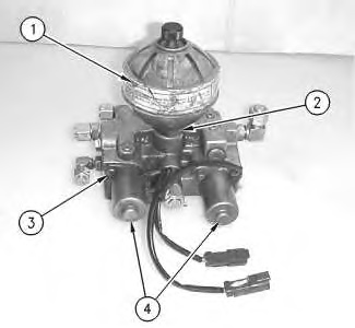
- Loosen nut (2) and remove accumulator (1). Remove hex head bolts (3) and solenoid assemblies (4) .
|
|
|
|
|
|
| Illustration 1 | g00889457 |
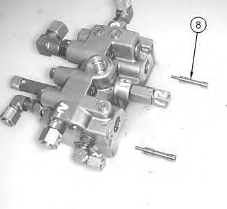
- Remove plates (7) and plungers (6) from solenoid assemblies (4) .
|
|
|
|
|
|
| Illustration 2 | g00889491 |
|
Plungers (6) and plates (7) are nonserviceable. |
|
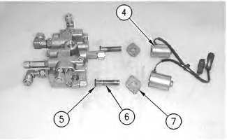
- Remove O-ring seals (5) from plungers (6) .
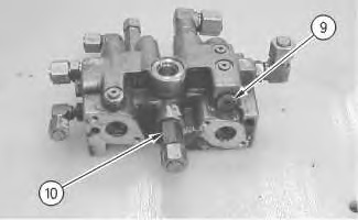
- Remove plug (9) and fitting (10). Remove the O-ring seal from fitting (10) .
|
|
|
|
|
|
| Illustration 4 | g00889824 |
|
Personal injury can result from parts and/or covers under spring pressure. Spring force will be released when covers are removed. Be prepared to hold spring loaded covers as the bolts are loosened. |
|
|
|
|
|
|
| Illustration 5 | g00889833 |
|
Valve (12) is nonserviceable. |
|
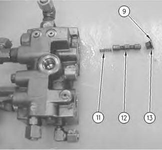
- Remove valve (12) and spring (11). Remove O-ring seal (13) from plug (9) .
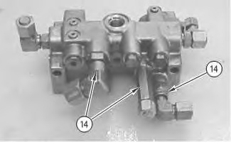
- Remove fittings (14) from the manifold. Remove the O-ring seals from fittings (14) .
|
|
|
|
|
|
| Illustration 6 | g00889898 |
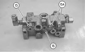
- Remove plug (15). Remove the O-ring seal from plug (15) .
|
|
|
|
|
|
| Illustration 7 | g00889922 |
|
Personal injury can result from parts and/or covers under spring pressure. Spring force will be released when covers are removed. Be prepared to hold spring loaded covers as the bolts are loosened. |
|
|
|
|
|
|
| Illustration 8 | g00889994 |
- Remove plugs (15A). Remove the O-ring seals from plugs (15A) .
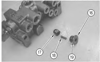
- Remove plug (16) .
- Remove spring (18) and valve (17) from the manifold. Remove O-ring seal (19) from plug (16) .
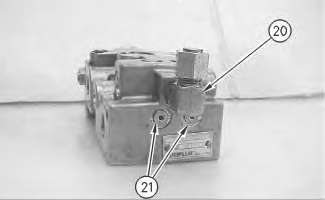
- Remove fitting (20) and plugs (21) from the manifold. Remove the O-ring seals from fitting (20) and from plugs (21) .
|
|
|
|
|
|
| Illustration 9 | g00890036 |