|
|
|
|
|
|
| Illustration 1 | g00756461 |
|
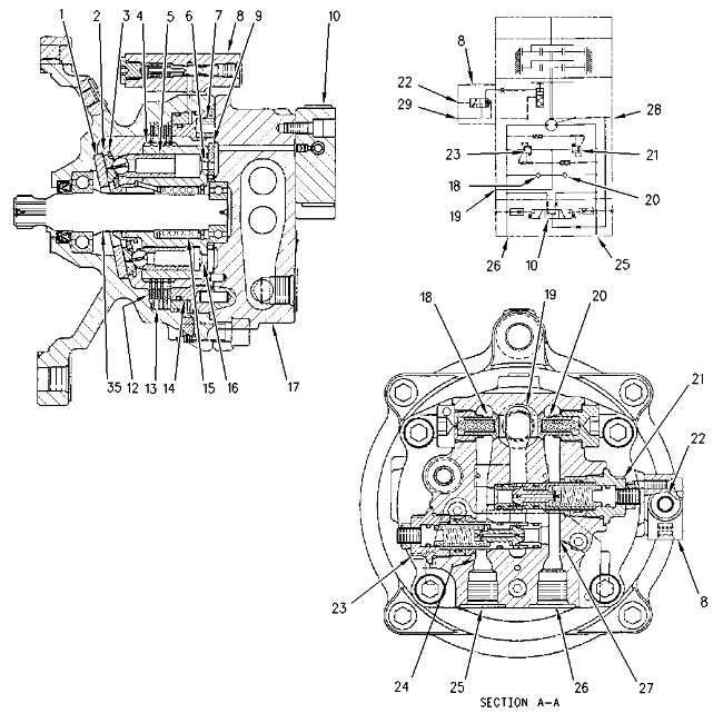
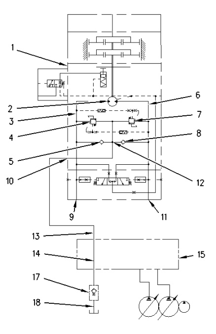
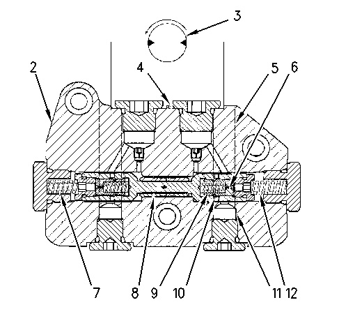
Swing motor (1) Cam plate (2) Shoe (3) Retainer plate (4) Cylinder barrel (5) Piston (6) Passage (7) Spring (8) Control valve for swing parking brake (9) Valve plate (10) Anti-reaction valve (12) Friction plate (13) Plate (14) Piston (15) Spring (16) Passage (17) Cover (18) Check valve (19) Makeup port (20) Check valve (21) Relief valve (22) Port (23) Relief valve (24) Passage (25) Port (26) Port (27) Passage (28) Drain port (29) Port |
|
Introduction
The swing motor may be divided into the following four groups:
- The rotary group consists of the following components: cylinder barrel (4), pistons (5), shoes (2) and retainer plate (3) .
- The parking brake consists of the following components: springs (7), piston (14), plate (13), friction plate (12) and control valve for swing parking brake (8) .
Note: For more information about the parking brake, refer to Systems Operation, “Pilot Valve (Swing Parking Brake)”.
- The relief valve and the makeup valve consists of the following components: relief valve (23), relief valve (21), check valve (18) and check valve (20) .
- The anti-reaction valve group consists of the following component: anti-reaction valves (10) .
Operation
|
|
|
|
|
|
| Illustration 2 | g00756518 |
|
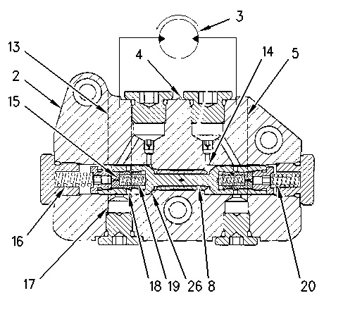
Motor passages (A) Bottom center position (B) Outlet side (low pressure) (C) Inlet side (high pressure) (D) Top center position (24) Passage (25) Port (26) Port (27) Passage (30) Counterclockwise turn (31) Passage (valve plate) (32) Passage (cylinder barrel) (33) Passage (cylinder barrel) (34) Passage (valve plate) |
|
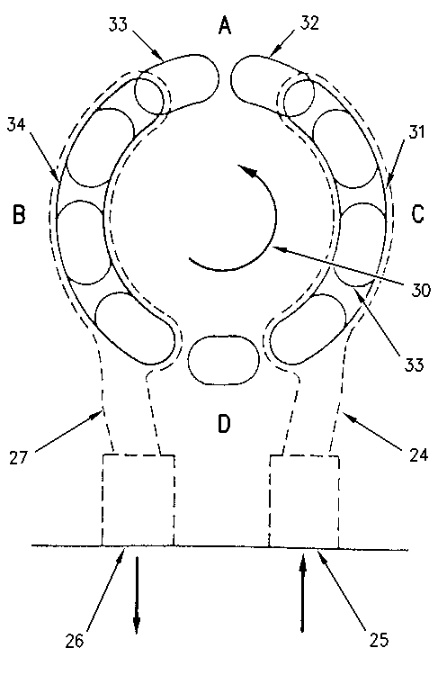
Right pump oil passes through the swing control valve and the oil is directed to port (25) and port (26) .
For a SWING RIGHT operation, right pump oil enters port (25). The oil then goes through passage (24) and passage (31) in cover (17). Oil then goes through passage (31) in valve plate (9) and through passage (33) in cylinder barrel (4) .
Pump oil in cylinder barrel (4) acts against piston (5). This forces piston (5) out of cylinder barrel (4) and the oil also forces shoe (2) against cam plate (1). The piston and the shoe slide on the inclined surface of cam plate (1) from the top dead center to bottom dead center as cylinder barrel (4) rotates.
Shoe (2) and piston (5) act against cam plate (1). This force causes cylinder barrel (4) to rotate counterclockwise. As each piston reaches the bottom center position, passage (33) is opened to passage (34) in valve plate (9). Oil flows through passage (27) into cover (17). The oil then returns to the hydraulic tank through port (25). As cylinder barrel (4) continues to rotate counterclockwise, the piston and the shoe continue to move up the inclined surface of the cam plate (1) .
For a SWING LEFT operation, right pump oil is supplied to port (26). The supply ports and the return ports are reversed. Cylinder barrel (4) turns clockwise.
The case drain oil from the swing motor returns through drain port (28) of cover (17) and flows to the hydraulic tank.
Swing Parking Brake
|
|
|
|
|
|
| Illustration 3 | g00756529 |
|
Swing Parking Brake (release) (1) Control valve for the swing parking brake (2) Spring (3) Spool (4) Port (5) Port (6) Housing (7) Piston (8) Spring (9) Cylinder (10) Friction plate (11) Separator plate (12) Passage (13) Piston chamber |
|
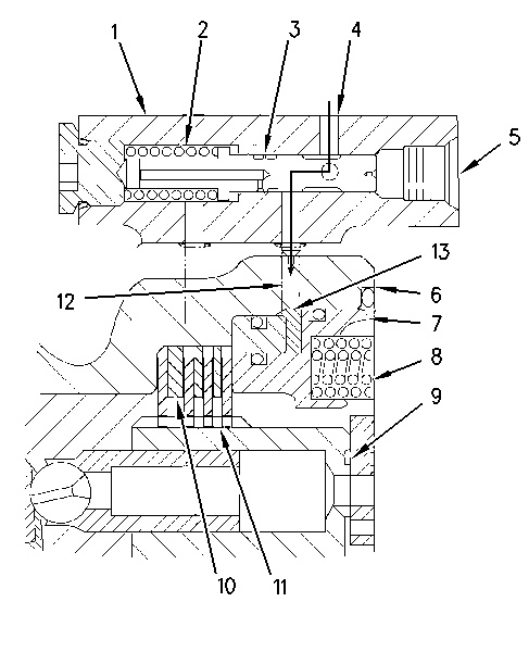
The swing parking brake is located in housing (6). The swing parking brake is made up of spring (8), piston (7), friction plate (10), separator plate (11) and control valve (1) for swing parking brake.
Teeth on the inner circumference of friction plate (10) engage with splines on cylinder (9). Teeth on the outer circumference of separator plate (11) engage with splines on the inner circumference of housing (6). Friction plate (10) and separator plate (11) are free to move to axial direction.
When you move the swing control lever, the oil that is flowing through port (5) of control valve (1) will increase. The increased pilot oil pressure moves spool (3) to the left against the force of spring (2). The opening of passage (12) allows pilot oil from port (4) to flow through passage (12). Pilot oil goes through passage (12) to piston chamber (13). The pilot oil in piston chamber (13) causes piston (7) to move to the right which compresses spring (8). The force that holds separator plate (11) and friction plate (10) together is released. The swing parking brake is released and the upper structure is free to swing.
|
|
|
|
|
|
| Illustration 4 | g00756536 |
|
Swing Parking Brake (operation) (1) Control valve for the swing parking brake (2) Spring (3) Spool (4) Port (5) Port (6) Housing (7) Piston (8) Spring (9) Cylinder (10) Friction plate (11) Separator plate (12) Passage (13) Piston chamber (14) Orifice (15) Spring (16) Passage |
|
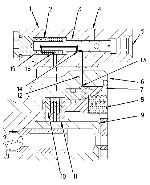
When the swing control is in the NEUTRAL position, the pilot oil pressure to port (5) decreases. Spool (3) is moved to the right by force of spring (2) which closes port (4). Spool (3) blocks pilot oil flow from port (4) to piston chamber (13) through passage (12). Piston (7) is shifted to the left by the force of spring (8). When piston (3) is shifted, the oil in piston chamber (13) goes through passage (12) and orifice (14) into spring chamber (15) .
Pilot oil from passage (12) is restricted at orifice (14). Pilot oil in spring chamber (15) slowly flows through passage (16) to the motor case drain. As piston (7) slowly moves to the left, friction plate (10) and separator plate (11) are forced together against housing (6). Cylinder (9) is held from rotating, which prevents rotation of upper structure.
Since the restricted oil flow delays the activation of the parking brake, the parking brake is applied after the swing operation has been stopped. This prevents damage and unusual wear to the parking brake.
Relief/Makeup Operation
|
|
|
|
|
|
| Illustration 5 | g00756555 |
|
Partial schematic of swing circuit (1) Swing motor (2) Motor rotary group of the swing motor (3) Passage (4) Relief valve (5) Check valve (6) Passage (7) Relief valve (8) Check valve (9) Port (10) Makeup port (11) Port (12) Passage (13) Makeup line (14) Return passage (15) Main control valve (17) Slow return check valve (18) Return line |
|
|
|
|
|
|
|
| Illustration 6 | g00862137 |
|
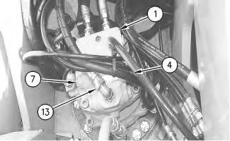
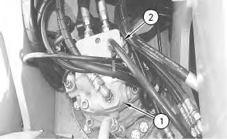
Swing motor compartment (1) Swing motor (4) Relief valve (7) Relief valve (13) Makeup line |
|
Relief Valve
|
|
|
|
|
|
| Illustration 7 | g00756566 |
|
Relief valve (6) Passage (7) Relief valve (12) Passage (19) Passage (20) Spring chamber (21) Piston (22) Passage (23) Sleeve (25) Spring (26) Valve |
|
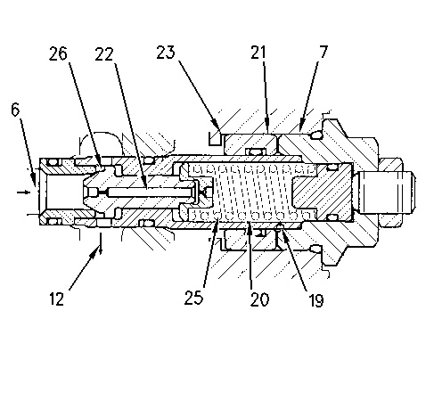
Relief valves (4) and (7) are located in the top of swing motor (1). The relief valves limit the pressure in the swing circuit to the relief valve pressure setting. This provides a cushion effect at a start or stop of the swing operation.
When the swing control lever is moved back to the NEUTRAL position from the SWING RIGHT position, both the inlet and outlet ports of the swing control valve are closed. No oil flow is supplied to port (9). This blocks the oil flow from port (11) to the swing control valve. The mass (weight and size) of the upper structure causes the swing motor to rotate after the control lever is in the NEUTRAL position. The swing motor attempts to draw oil from port (9) and attempts to force the oil out of port (11). Since port (11) is closed, the pressure of the blocked oil in passage (6) increases. The increased pressure oil in passage (6) shifts valve (26) to the right (open position). Valve (26) shifts against the forces of spring (25) in relief valve (7). When valve (26) shifts, oil flows through passage (12) and check valve (5) to passage (3). From passage (3), oil enters the motor rotary group (2). The force of the rotating upper structure is absorbed at a stop of swing movement.
The oil in passage (6) goes through passage (22) of valve (26) and spring chamber (20) to passage (19). Because the force of spring (25) is less than the relief valve pressure setting 22100 kPa (3200 psi), valve (26) opens just before the oil pressure in passage (6) reaches the relief valve pressure setting. When valve (26) opens, the oil in passage (6) is allowed to vent. At the same time, the pressure oil in passage (19) moves piston (21) to the left. This compresses spring (25) until the left face of piston (21) comes in contact with sleeve (23). For approximately 0.3 seconds of the piston movement, the oil pressure in passage (19) is lower than the relief valve pressure setting. When piston (21) stops movement to the left, the oil pressure in passage (6) increases to the relief valve pressure setting of 22100 kPa (3200 psi). All of the oil is allowed to flow from relief valve (26) to passage (12) when the relief valve pressure setting is reached.
The two-stage relief action prevents a peak pressure buildup when relief valve (26) opens. This produces less shock load when the swing motor comes to a stop. The force of the rotating upper structure is absorbed as the swing motor comes to a stop.
After the start of a SWING RIGHT operation, the mass (weight and size) of the upper structure causes an increase of oil pressure at port (9). Part of the oil flows through relief valve (4) and through makeup port (10) to return line (18). This gives a smoother acceleration at the start of a swing operation.
Oil Makeup Operation
When the rotation of the swing motor is stopped, both the inlet and the outlet ports of the swing control valve are blocked. No pump oil is sent to the swing motor. The mass (weight and size) of the upper structure causes the upper structure to attempt to continue rotation. Part of the oil in the swing motor is lost in the form of internal leakage. The oil loss causes a vacuum condition to occur at port (9). To prevent this vacuum condition, oil from return line (14) goes through makeup line (13), makeup port (10), check valve (5) and passage (3) into the motor rotary group (2) .
Slow Return Check Valve
Slow return check valve (17) is located on the return side of return line (14). Valve (17) provides makeup oil that is lost during a swing stop.
When main control valve (15) is in the NEUTRAL position, the oil from the right and left pumps goes through return line (14) to the hydraulic tank. Slow return check valve (17) is set to open at 290 kPa (43 psi). Valve (17) causes a resistance to the oil flow in return line (14) in order to maintain the oil pressure at approximately 290 kPa (43 psi). When insufficient oil is supplied to the swing motor, oil flow is added to the motor rotary group through makeup line (13), makeup port (10) and passage (3) .
Note: For more information about the slow return check valve, refer to Systems Operation, “Return Hydraulic System”.
A partial movement of the swing control lever to the NEUTRAL position during a high speed right swing causes oil supply from port (9) to decrease. Since the swing control valve is partially open, the oil flow continues to flow through port (11) to return line (14). The oil pressure at port (11) is lower than the pressure setting of relief valve (7). Relief valve (7) is kept closed. This blocks makeup oil flow through check valve (5) to passage (3). A vacuum condition occurs at port (9). This causes check valve (5) to supply makeup oil from makeup line (13) to the motor rotary group (2). This oil supply causes the vacuum condition at port (9) to be eliminated.
When the swing motor is stopped or decelerated during a swing operation in the opposite direction, oil is supplied through port (11) and check valve (8). Check valve (8) operates in the same manner as check valve (5). Check valve (8) prevents a vacuum condition in the swing motor.
Anti-Reaction Valve
|
|
|
|
|
|
| Illustration 8 | g00862140 |
|
Top view of swing motor (1) Swing motor (2) Anti-reaction valve |
|
At a stop of swing operation, it is difficult to smoothly stop the upper structure and implements at the desired position. This is due to the mass (weight and size) of the upper structure. The oil that is blocked in the outlet side of the swing motor goes to the motor rotary group. This causes the upper structure to swing in the reverse direction. Anti-reaction valve (2) is installed on swing motor (1) in order to prevent the upper structure from swinging backward.
|
|
|
|
|
|
| Illustration 9 | g00756601 |
|
Anti-Reaction valve (swing operation) (2) Anti-Reaction valve (3) Motor rotary group of the swing motor (4) Body (5) Passage (6) Orifice (7) Spring (8) Valve (9) Spring chamber (10) Passage (11) Passage (12) Spring |
|
When the motor rotary group (3) gets pump oil through passage (5), the motor rotary group rotates clockwise. The oil in passage (5) also goes through passage (11), passage (10), spring chamber (9) and orifice (6) into spring chamber (12). Oil pressure in spring chamber (12) moves valve (8) to the left against the force of spring (7). Valve (8) moves to the left until contact is made with body (4).
|
|
|
|
|
|
| Illustration 10 | g00756613 |
|
Anti-Reaction valve (swing stop) (2) Anti-Reaction valve (3) Motor rotary group of the swing motor (4) Body (5) Passage (8) Valve (13) Passage (14) Seat (15) Orifice (16) Spring chamber (17) Passage (18) Passage (19) Spring chamber (20) Spring chamber (26) Seat |
|
When pump oil is not supplied to passage (5), motor rotary group (3) continues to rotate clockwise. The rotation is caused by the mass (weight and size) of the upper structure. The oil pressure that is blocked in passage (13) increases and the oil pressure in spring chamber (20) decreases. The increased oil pressure in passage (13) goes through passage (17), passage (18), spring chamber (19), and orifice (15). The oil then enters spring chamber (16). The oil pressure in spring chamber (16) moves valve (8) to the right against the force of spring (20) until valve (8) comes in contact with seat (26) of body (4). Valve (8) comes off seat (14) in body (4) .
When the inertia of the upper structure is stopped by the closed pressure in passage (13), the motor rotary group (3) stops. Motor rotary group (3) rotates in a reverse direction (counterclockwise direction). This rotation is due to gear backlash. The oil pressure in passage (5) increases and the oil pressure in passage (13) decreases.