C27 and C32 Generator Set Engines Troubleshooting Page 103
Troubleshooting
RENR9348-01 103
Troubleshooting Section
g01209787
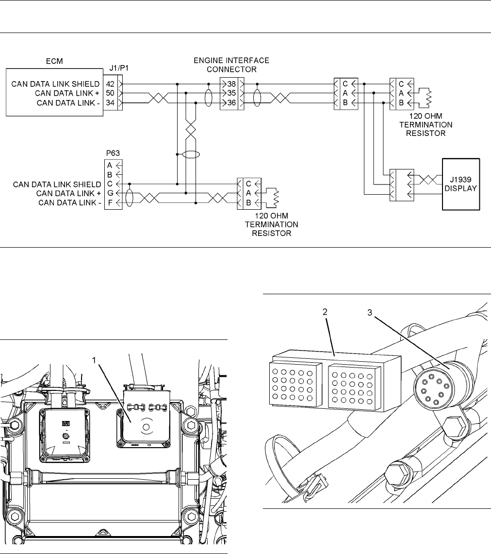
Illustration 1 8
Schematic for the CA N data link
Test Step 1. Inspect the Electrical
Connectors and the Wiring
A. Turn the keyswitch to the OFF position.
g01167488
Illustration 19
Location o f the ECM (typical engine v iew)
(1) J1/P1 ECM conntctors
g01207179
Illustration 20
Location of the e ngine interface connector and the service tool
connector (typical engine view)
(2) Engine interface connector
(3) Service tool connector
B. Thoroughly inspect connectors (1), (2), and (3).
Thoroughly inspect the connectors for each
module that is connected to the CAN data link.
Refer to T roubleshooting, “Electrical Connectors
- Inspect”.
Contents Summary of C27 and C32 Generator Set Engines Troubleshooting
- Page 1RENR9348-01 January 2007 Troubleshooting C27 and C32 Generator Set Engines DWB1-Up (Generator Set) SXC1-Up (Generator Set) MED1-Up (Power Module) MEG1-Up (Power Module) WDR1-Up (Generator Set)�
- Page 2i01658146 Important Safety Information Most accidents that involve product operation, maintenance and repair are caused by failure to observe basic safety rules or precautions. An accident can often be avoided by recognizing potentially hazardous situations before an accident occurs. A person must b
- Page 3RENR9348-01 3 Table of Contents Table of Contents CID 0002 FMI 05 Cylinder #2 Injector open circuit ................................................................... 54 CID 0002 FMI 06 Cylinder #2 Injector short ......... 54 CID 0003 FMI 05 Cylinder #3 Injector open Troubleshooting Section circuit
- Page 44 RENR9348-01 Table of Contents CID 0175 FMI 04 Engine Oil Temperature short to Engine Pressure Sensor Open or Short Circuit - ground ................................................................. 66 Test ................................................................... 131 CID 0190 FMI 08 Engi
- Page 5RENR9348-01 5 Troubleshooting Section Troubleshooting Section Cold Mode The ECM limits engine power during cold mode operation. Injection timing is also modified during Electronic Troubleshooting cold mode operation. Cold mode operation provides the following benefits: i02436970 • Increased cold wea
- Page 66 RENR9348-01 Troubleshooting Section Once the ECM calculates the amount of fuel that Table 1 is required for the engine, the timing of the fuel Required Service Tools injection cycle must be calculated. The ECM receives information about the top center position of each Part Description cylinder fro
- Page 7RENR9348-01 7 Troubleshooting Section Caterpillar Electronic Technician Table 4 (ET) Standard Hardware for the Use of Cat ET Part Number Description Cat ET can display the following information: N/A Personal Computer (PC) • Parameters Communication Adapter • Event codes 171-4400(1) Gp (CAT ET TO ECM
- Page 88 RENR9348-01 Troubleshooting Section a. Connect cable (4) between the “COMPUTER” end of communications adapter (5) and the parallel port of PC (1). Be sure to configure Cat ET for the parallel port. This configuration provides the fastest connection. b. Connect cable (3) between the “COMPUTER” end
- Page 9RENR9348-01 9 Troubleshooting Section i02518796 1. Print the parameters from the “Configuration” screen on Caterpillar Electronic Technician Replacing the ECM (ET). If a printer is unavailable, record all of the parameters. Record any logged diagnostic codes SMCS Code: 1901-510 and logged event code
- Page 1010 RENR9348-01 Troubleshooting Section a. If the old mounting hardware is in good repair, Note: If the “Copy Configuration” process fails and you can use the old mounting hardware to the parameters were not obtained in Step 1, the install the replacement ECM. parameters must be obtained elsewhere. S
- Page 11RENR9348-01 11 Troubleshooting Section Every generated code is stored in the permanent memory of the ECM. The codes are logged. Logged codes may not indicate that a repair is needed. The problem may have been temporary. The problem may have been resolved since the logging of the code. If the system
- Page 1212 RENR9348-01 Troubleshooting Section i02409268 Sensors and Electrical Connectors SMCS Code: 1439; 7553-WW g01203891 Illustration 3�
- Page 13RENR9348-01 13 Troubleshooting Section Block diagram C27 and C32 Engines g01204004 Illustration 4 Component locations (typical left side engine view) (1) Atmospheric pressure sensor (6) Termination resistor (11) Engine oil temperature sensor (2) Engine coolant temperature sensor (7) Service tool con
- Page 1414 RENR9348-01 Troubleshooting Section g01203895 Illustration 5 Component locations (typical right side engine view) (15) Electronic Control Module (ECM) (18) Secondary engine speed/timing sensor (21) Fuel pressure sensor (16) J2/P2 ECM connector (19) Engine oil pressure sensor (22) Fuel temperature
- Page 15RENR9348-01 15 Troubleshooting Section i02433503 Table 7 Engine Wiring Information Metric Equivalents for AWG Numbers AWG Diameter AWG Diameter SMCS Code: 1408 Number (mm) Number (mm) The wiring schematics are revised periodically. 20 0.8 14 1.6 The wiring schematics will change as updates are 18 1.
- Page 1616 RENR9348-01 Troubleshooting Section g01143634 Illustration 6 Service welding guide (typical diagram) 3. Connect the welding ground cable as close as possible to the area that will be welded. Components which may be damaged by welding include bearings, hydraulic components, and electrical/electron
- Page 17RENR9348-01 17 Troubleshooting Section Programming Parameters 2. Use the “Copy Configuration/ECM Replacement” feature on Cat ET to copy the configuration parameters from the suspect ECM to your personal i02253984 computer (PC). If the “Copy Configuration/ECM Replacement” feature cannot be used, reco
- Page 1818 RENR9348-01 Troubleshooting Section If the new ECM does not fix the problem, the i02193979 original ECM is not the problem. Remove the new ECM before the 24 hour timer expires. Reconnect Factory Passwords Worksheet the original ECM. SMCS Code: 0785 i02433393 Note: A mistake in recording this info
- Page 19RENR9348-01 19 Troubleshooting Section Programming a Flash File • The ECM is replaced. 1. Establish communication between Cat ET and the • “Injector Trim” is displayed below a 268-02 engine’s ECM. diagnostic code on Cat ET. 2. Select “WinFlash” from the “Utilities” menu on Cat • Injectors are exchan
- Page 2020 RENR9348-01 Troubleshooting Section The injector trim file is loaded into the ECM. 13. Repeat the procedure for each cylinder, as required.�
- Page 21RENR9348-01 21 Troubleshooting Section System Configuration Test Spec Parameters This is the engine’s “Test Specifiction Number”. Use this number to retrieve data that is related to the engine’s specifications from the Technical Marketing i02421358 Information System (TMI). The following information
- Page 2222 RENR9348-01 Troubleshooting Section Total Tattletale Number of Crank Cycles The total tattletale counts the number of changes to This parameter defines the number of crank cycles system parameters. for the engine. Engine Accel. Rate Engine Oil Temperature Sensor Installation Status This parameter
- Page 23RENR9348-01 23 Troubleshooting Section Remote Emergency Stop Switch Input Digital Speed Control Min Speed Type Configuration This parameter is used to configure the engine speed This parameter sets the installation status and the below the rated speed of the engine. configuration of the emergency st
- Page 2424 RENR9348-01 Troubleshooting Section Parameter Table Table 9 System Configuration Parameters Required Parameter Available Range or Options Default Password Selected Engine Ratings Rating Number Software Dependent None Rated Frequency Software Dependent Read Only(1) Rated Engine Speed Software Depe
- Page 25RENR9348-01 25 Troubleshooting Section (Table 9, contd) System Configuration Parameters Required Parameter Available Range or Options Default Password Uninstalled Fuel Filter Differential Pressure Switch Normally Open Uninstalled Customer Configuration Normally Closed Emergency Shutdown Override Swi
- Page 2626 RENR9348-01 Troubleshooting Section (Table 10, contd) Parameter Worksheet Droop mode selection Ether Control Prelube Duration Cranking Duration Maximum Number of Crank Cycles Desired Speed Input Configuration Engine State Control Configuration Cooldown Duration Secondary Desired Speed Input Confi
- Page 27RENR9348-01 27 Troubleshooting Section Troubleshooting without a i02422398 Diagnostic Code Can Not Reach Top Engine RPM i02121176 SMCS Code: 1915-035 Alternator Note: If the problem occurs during high engine loads (Charging Problem) then refer to Troubleshooting, “Low Power/Poor or No Response to Th
- Page 2828 RENR9348-01 Troubleshooting Section 2. Monitor the status of the intake manifold pressure Accessory Equipment sensor on Cat ET for normal operation. Ensure that the status for the “Boost Pressure” parameter Check all accessory equipment for problems that is reasonable. Ensure that the intake mani
- Page 29RENR9348-01 29 Troubleshooting Section Cylinder Liner i02480112 Check for cracked cylinder liners. Replace any ECM Will Not Communicate cracked cylinder liners. Refer to the Disassembly and with Other Systems or Display Assembly manual. Modules Cylinder Block SMCS Code: 1901-035 Inspect the cylinder
- Page 3030 RENR9348-01 Troubleshooting Section • Caterpillar Electronic Technician (ET) and related 2. Disconnect the communication adapter and the hardware cables from the service tool connector. Reconnect the communication adapter to the service tool • Electrical power supply to the Electronic Control con
- Page 31RENR9348-01 31 Troubleshooting Section i02475556 Starting Motor, Solenoid, or Starting Engine Cranks but Will Not Circuit Start Remove the starter and visually inspect the pinion of the starter and the flywheel ring gear for damage. SMCS Code: 1000-035 Test the operation of the starting motor soleno
- Page 3232 RENR9348-01 Troubleshooting Section 3. Check the fuel tank for foreign objects which may Recommended Actions block the fuel supply. Incorrect Engine Oil 4. Prime the fuel system if any of the following procedures have been performed: Use engine oil that is recommended and change the engine oil at
- Page 33RENR9348-01 33 Troubleshooting Section i02513923 Throttle Signal Engine Misfires, Runs Rough Monitor throttle signal on Cat ET. Verify that the or Is Unstable throttle signal is stable from the low idle position to the high idle position. SMCS Code: 1000-035 Unit Injectors Note: If the symptom is in
- Page 3434 RENR9348-01 Troubleshooting Section 2. Check the air inlet and exhaust system for • Air supply restrictions and/or leaks. Refer to Systems Operation/Testing and Adjusting, “Air Inlet and • Engine idle Exhaust System”. • Accessory equipment i02173692 Recommended Actions Engine Oil in Cooling Syste
- Page 35RENR9348-01 35 Troubleshooting Section 5. Cold weather adversely affects the characteristics Engine Supports of the fuel. Refer to the Operation and Maintenance Manual. Inspect the mounts and the brackets while you run the engine through the speed range. Look for mounts 6. Check the fuel pressure af
- Page 3636 RENR9348-01 Troubleshooting Section Batteries and/or Battery Cables 2. Inspect the pinion for the starting motor and the flywheel ring gear for damage. 1. Inspect the battery posts, and battery cables for loose connections and for corrosion. If the battery Engine Accessories cables are corroded,
- Page 37RENR9348-01 37 Troubleshooting Section • Valve adjustment Note: A problem with the “FRC Fuel Limit” will only cause black smoke during acceleration. A problem with the “FRC Fuel Limit” will not cause black smoke Recommended Actions during steady state operation. Air Inlet or Exhaust System Flash Fil
- Page 3838 RENR9348-01 Troubleshooting Section Turbocharger Fuel Leaks Check for turbocharger shaft seal leakage. Remove Check the fuel pressure during engine cranking. the air inlet piping and the exhaust outlet piping from Check the fuel pressure after the fuel filter. Refer the turbocharger. Check the co
- Page 39RENR9348-01 39 Troubleshooting Section i02285926 i02399564 Excessive Valve Lash Excessive White Smoke SMCS Code: 1105-035 SMCS Code: 1088-035 Note: Some white smoke may be present during Probable Causes cold start-up conditions when the engine is operating normally. If the white smoke persists, ther
- Page 4040 RENR9348-01 Troubleshooting Section 2. Verify that the timing of the crankshaft and i02281012 camshaft drive gears are set with the proper orientation. Refer to Disassembly and Assembly Fuel in Cooling System for information that is related to the correct gear installation. SMCS Code: 1350-035 Th
- Page 41RENR9348-01 41 Troubleshooting Section Excessive Leakage from the Unit Injector Electrical Connectors Tip or a Broken Unit Injector Tip 1. Check for correct installation of the J1/P1 and Look for signs of damage to the unit injectors. J2/P2 connectors for the Electronic Control Module If necessary,
- Page 4242 RENR9348-01 Troubleshooting Section 5. Check fuel quality. Cold weather adversely Throttle Signal affects the characteristics of the fuel. Refer to the Operation and Maintenance Manual. Monitor the status for “Throttle Position” on Cat ET. Verify that the status for “Throttle Position” is stable
- Page 43RENR9348-01 43 Troubleshooting Section i02430113 Fuel Dilution Low Engine Oil Pressure Check for presence of fuel in lubricating oil. Refer to the troubleshooting without a diagnostic code SMCS Code: 1348-035-LP procedure Troubleshooting, “Fuel Dilution of Engine Oil”. NOTICE Do not operate engine w
- Page 4444 RENR9348-01 Troubleshooting Section Certain diagnostic codes and/or event codes may Table 11 cause poor performance. Use Cat ET to check for “Fuel Position” = “Rated Fuel Limit” active codes and for logged codes. Troubleshoot any codes that are present before continuing with this and procedure. “
- Page 45RENR9348-01 45 Troubleshooting Section 1. Isolate the source of the noise. Remove NOTICE the suspect engine accessories. Inspect Do not crank the engine continuously for more than the suspect engine accessories. Repair the 30 seconds. Allow the starting motor to cool for two engine accessories and/o
- Page 4646 RENR9348-01 Troubleshooting Section Unit Injectors Recommended Actions 1. Check the connectors at the Electronic Control Note: If the problem only occurs under certain Module (ECM). Check for correct installation conditions, test the engine under those conditions. of the J1/P1 and J2/P2 ECM conne
- Page 47RENR9348-01 47 Troubleshooting Section Unit Injectors 3. Check the fuel tank for debris or foreign objects which may block the fuel supply. 1. Perform the “Injector Solenoid Test” on Cat ET in order to determine if all of the injector solenoids NOTICE are being energized by the ECM. Do not crank the
- Page 4848 RENR9348-01 Troubleshooting Section Recommended Actions Valve components 1. A valve rotator that is cracked or a valve rotator that is broken is an indication of an engine overspeed. Determine the cause of the engine overspeed. Repair the condition. 2. Inspect the following components for damage:
- Page 49RENR9348-01 49 Troubleshooting Section Troubleshooting with a Diagnostic Code i02432846 Diagnostic Codes SMCS Code: 1900 Diagnostic Codes Diagnostic codes alert the operator that a problem in the electronic system has been detected. Diagnostic codes also indicate the nature of the problem to the ser
- Page 5050 RENR9348-01 Troubleshooting Section Logged Diagnostic Codes For information on event codes, refer to Troubleshooting, “Event Codes”. When the ECM generates a diagnostic code, the ECM logs the code in permanent memory. The ECM has an internal diagnostic clock. Each ECM will record the following in
- Page 51RENR9348-01 51 Troubleshooting Section Cross-Reference for SPN-FMI Code to CID-FMI Table 13 Cross-Reference for SPN-FMI Code to CID-FMI SPN/FMI CID-FMI Description of Code 91-08 91-08 Throttle Position signal abnormal 94-03 94-03 Fuel Pressure open/short to +batt 94-04 94-04 Fuel Pressure short to g
- Page 5252 RENR9348-01 Troubleshooting Section (Table 13, contd) Cross-Reference for SPN-FMI Code to CID-FMI SPN/FMI CID-FMI Description of Code 654-06 4-06 Cylinder #4 Injector short 655-05 5-05 Cylinder #5 Injector open circuit 655-06 5-06 Cylinder #5 Injector short 656-05 6-05 Cylinder #6 Injector open c
- Page 53RENR9348-01 53 Troubleshooting Section Cross-Reference for SPN-FMI Code to EID Table 14 Cross-Reference for SPN-FMI Code to EID SPN/FMI EID Description of Code 16-17 E390-1 Fuel Filter Restriction Warning 16-19 E390-2 Fuel Filter Restriction Derate 16-01 E390-3 Fuel Filter Restriction Shutdown 94-15
- Page 5454 RENR9348-01 Troubleshooting Section i02430358 Troubleshooting: CID 0001 FMI 05 Cylinder #1 Perform the following diagnostic procedure: “Injector Injector open circuit Solenoid Circuit - Test” SMCS Code: 1290-038 Results: Conditions Which Generate This Code: • OK – STOP. The Electronic Control Mod
- Page 55RENR9348-01 55 Troubleshooting Section System Response: i02430366 The ECM will log the diagnostic code. The ECM will CID 0003 FMI 06 Cylinder #3 continue to attempt to operate the injector after the Injector short code has been logged. SMCS Code: 1290-038 Possible Performance Effect: Conditions Whic
- Page 5656 RENR9348-01 Troubleshooting Section Troubleshooting: System Response: Perform the following diagnostic procedure: “Injector The ECM will log the diagnostic code. The ECM will Solenoid Circuit - Test” continue to attempt to operate the injector after the code has been logged. Results: Possible Per
- Page 57RENR9348-01 57 Troubleshooting Section i02430375 Troubleshooting: CID 0006 FMI 05 Cylinder #6 Perform the following diagnostic procedure: “Injector Injector open circuit Solenoid Circuit - Test” SMCS Code: 1290-038 Results: Conditions Which Generate This Code: • OK – STOP. The Electronic Control Mod
- Page 5858 RENR9348-01 Troubleshooting Section Possible Performance Effect: i02420872 • Engine misfires CID 0008 FMI 06 Cylinder #8 Injector short • Low power SMCS Code: 1290-038 Troubleshooting: Conditions Which Generate This Code: Perform the following diagnostic procedure: “Injector Solenoid Circuit - Te
- Page 59RENR9348-01 59 Troubleshooting Section Troubleshooting: Possible Performance Effect: Perform the following diagnostic procedure: “Injector • Engine misfires Solenoid Circuit - Test” • Low power Results: Troubleshooting: • OK – STOP. Perform the following diagnostic procedure: “Injector Solenoid Circ
- Page 6060 RENR9348-01 Troubleshooting Section System Response: i02420764 The ECM will log the diagnostic code. The ECM will CID 0012 FMI 05 Cylinder #12 continue to attempt to operate the injector after the Injector open circuit code has been logged. SMCS Code: 1290-038 Possible Performance Effect: Conditi
- Page 61RENR9348-01 61 Troubleshooting Section Troubleshooting: System Response: Perform the following diagnostic procedure: “Injector The code is logged. The ECM flags fuel pressure as Solenoid Circuit - Test” invalid data and a default value is used. Results: Possible Performance Effect: • OK – STOP. • Th
- Page 6262 RENR9348-01 Troubleshooting Section System Response: i02581776 The code is logged. The ECM flags oil pressure as CID 0100 FMI 10 Engine Oil invalid data and a default value is used. Pressure Sensor abnormal Possible Performance Effect: rate of change • There are no performance effects. SMCS Code:
- Page 63RENR9348-01 63 Troubleshooting Section i02427669 • The engine may experience reduced speed (rpm) and/or low power. CID 0110 FMI 03 Engine Coolant Temperature Troubleshooting: open/short to +batt Perform the following diagnostic procedure: “Engine Temperature Sensor Open or Short Circuit - Test” SMCS
- Page 6464 RENR9348-01 Troubleshooting Section i02480880 Possible Performance Effect: CID 0168 FMI 01 System • An engine misfire may occur. Voltage Low • An engine shutdown condition may occur. SMCS Code: 1401-038 Troubleshooting: Conditions Which Generate This Code: Perform the following diagnostic procedu
- Page 65RENR9348-01 65 Troubleshooting Section i02424787 Troubleshooting: CID 0172 FMI 04 Intake Perform the following diagnostic procedure: “Engine Manifold Air Temp short to Temperature Sensor Open or Short Circuit - Test” ground Results: SMCS Code: 1439-038-AI; 1921-038 • OK – STOP. Conditions Which Gene
- Page 6666 RENR9348-01 Troubleshooting Section Possible Performance Effect: System Response: • There are no performance effects. The code is logged. Troubleshooting: Possible Performance Effect: Perform the following diagnostic procedure: “Engine • The engine may not start. Temperature Sensor Open/Short Cir
- Page 67RENR9348-01 67 Troubleshooting Section i02428636 i02437198 CID 0253 FMI 02 Personality CID 0261 FMI 11 Engine Timing Module mismatch Offset fault SMCS Code: 1902-038 SMCS Code: 1439-038; 1912-038 Conditions Which Generate This Code: Conditions Which Generate This Code: The flash file that is used fo
- Page 6868 RENR9348-01 Troubleshooting Section C. Ensure that the harness is properly secured, and Results: ensure that each tie-wrap is placed in the correct location. • OK – The condition of the gear train is OK. Expected Result: Repair: The problem is not in the gear train. Clear the diagnostic code. The
- Page 69RENR9348-01 69 Troubleshooting Section Results: Troubleshooting: • OK – STOP. Perform the following diagnostic procedure: “5 Volt Engine Pressure Sensor Supply Circuit - Test” i02416460 Results: CID 0262 FMI 03 5 Volt Sensor • OK – STOP. DC Power Supply short to +batt i02445689 SMCS Code: 1439-038 C
- Page 7070 RENR9348-01 Troubleshooting Section i02417898 i02407807 CID 0274 FMI 03 Atmospheric CID 0342 FMI 08 Secondary Pressure open/short to +batt Engine Speed signal abnormal SMCS Code: 1439-038-AI; 1923-038 SMCS Code: 1439-038-VF; 1907-038 Conditions Which Generate This Code: Conditions Which Generate
- Page 71RENR9348-01 71 Troubleshooting Section Results: i02418765 • OK – STOP. CID 0446 FMI 06 Air Shutoff Relay short i02418715 SMCS Code: 4493-038 CID 0444 FMI 06 Start Relay Conditions Which Generate This Code: short to ground The Electronic Control Module (ECM) detects an SMCS Code: 1426-038 excessive c
- Page 7272 RENR9348-01 Troubleshooting Section i02407894 Possible Performance Effect: CID 1785 FMI 04 Intake • Low power Manifold Pressure Sensor Troubleshooting: voltage low Repair the Sensor Supply Circuit SMCS Code: 1439-038-IL A. Repair the circuit for the supply wire between the Conditions Which Genera
- Page 73RENR9348-01 73 Troubleshooting Section Troubleshooting with an Event Code i02422406 Event Codes SMCS Code: 1901 Event codes alert the operator that an abnormal engine operating condition such as low oil pressure or high coolant temperature has been detected. When the event code is generated, this in
- Page 7474 RENR9348-01 Troubleshooting Section • E360-1 Low Oil Pressure Warning Troubleshooting • E360-2 Low Oil Pressure Derate For basic troubleshooting of the engine, perform the following steps in order to diagnose a malfunction: • E360-3 Low Oil Pressure Shutdown 1. Obtain the following information ab
- Page 75RENR9348-01 75 Troubleshooting Section Table 15 contains the conditions that are monitored and the default trip points for each condition. Each condition has an associated parameter. The settings for each parameter can be viewed with the Caterpillar Electronic Technician (ET). The trip points for so
- Page 7676 RENR9348-01 Troubleshooting Section Table 15 Trip Points for the Monitoring System Time Delay in Default Set Points Parameter Action Seconds Value Range Default Range Default E057 Low Engine Coolant Derate Off N/A N/A N/A N/A Level E059 Low Engine Coolant Warning Off 4 to 65 30 N/A N/A Level 758
- Page 77RENR9348-01 77 Troubleshooting Section (Table 15, contd) Trip Points for the Monitoring System Time Delay in Default Set Points Parameter Action Seconds Value Range Default Range Default E539 High Intake Manifold Warning On 75 °C (167 °F) N/A 8 N/A Air Temperature Derate Off 79 °C (174 °F) (1) Refer
- Page 7878 RENR9348-01 Troubleshooting Section Repair: There may be a problem with the coolant Note: If the coolant has been changed recently, level sensor. Refer to the diagnostic functional test ensure that the air has been purged from the Troubleshooting, “Coolant Level Sensor Circuit - cooling system. R
- Page 79RENR9348-01 79 Troubleshooting Section • The engine power is derated. • Intake manifold air temperature E096(3) • Barometric pressure • The engine is shut down. • Engine speed Troubleshooting: High intake manifold air temperature, high altitude operation, and high engine loads can cause the Check th
- Page 8080 RENR9348-01 Troubleshooting Section Repair: Clean the fins of the ATAAC. Clear the i02478132 event. Return the engine to service. E197 High Engine Oil STOP. Temperature • Not OK – The fins of the ATAAC are clear of SMCS Code: 1348-038-TA obstructions. Proceed to Test Step 3. Conditions Which Gene
- Page 81RENR9348-01 81 Troubleshooting Section Possible Performance Effect: B. Check the radiator or the heat exchanger for a restriction to coolant flow. E197-1 a. Check for debris or damage between the fins • Engine performance is not affected. of the radiator core. Debris between the fins of the radiator
- Page 8282 RENR9348-01 Troubleshooting Section J. Check for a restriction in the exhaust system. • There are no performance effects. A restriction of the air that is coming out of the engine can cause high cylinder temperatures. 198(2) K. Consider high ambient temperatures. When • The engine power is derate
- Page 83RENR9348-01 83 Troubleshooting Section i02342292 i02486798 E264 Emergency Stop E360 Low Engine Oil Pressure Activated SMCS Code: 1348-038-LP SMCS Code: 7418-038 Conditions Which Generate This Code: Conditions Which Generate This Code: The Electronic Control Module (ECM) detects a problem with the en
- Page 8484 RENR9348-01 Troubleshooting Section C. The inlet screen of the oil suction tube for the System Response: engine oil pump can have a restriction. This restriction will cause cavitation and a loss of The event code is logged. engine oil pressure. Check the inlet screen on the oil pickup tube and re
- Page 85RENR9348-01 85 Troubleshooting Section Clamps that are damaged and hoses that are c. If the air inlet system for this application leaking can usually be discovered during a is equipped with an aftercooler, check the visual inspection. aftercooler. A restriction of air flow through the air to air aft
- Page 8686 RENR9348-01 Troubleshooting Section System Response: Troubleshooting: The event code will be logged. Check the Fuel System Possible Performance Effect: Check the fuel system. E362(1) Expected Result: • There are no performance effects. A thorough inspection of the fuel system revealed a problem.
- Page 87RENR9348-01 87 Troubleshooting Section B. Restart the engine and check for an active event Perform the following Inspections code. A. Check for High Ambient Air Temperature Expected Result: a. Determine if the ambient air temperature is The event code is no longer active. within the design specifica
- Page 8888 RENR9348-01 Troubleshooting Section Repair: Repair the problem. Repair: Cycle the power to the ECM. Reset the air shutoff mechanism. Restart the engine. STOP. STOP. • Not OK – A thorough inspection did not reveal a problem. • Not OK - Engine Overspeed – An engine overspeed caused the shutdown. Re
- Page 89RENR9348-01 89 Troubleshooting Section Check the Programmable Parameters Determine the setting of the parameter. The Air Intake Shutoff Detection Circuit Detected but Not Installed parameter may need to be set to “Installed”. Results: • OK – STOP.
- Page 9090 RENR9348-01 Troubleshooting Section Diagnostic Functional Tests i02410077 5 Volt Engine Pressure Sensor Supply Circuit - Test SMCS Code: 1439-038 System Operation Description: Use this procedure to troubleshoot any suspect problems with the +5 V sensor supply. Use this procedure to troubleshoot t
- Page 91RENR9348-01 91 Troubleshooting Section g01204447 Illustration 9 Schematic for the pressure sensor supply Test Step 1. Inspect the Electrical Connectors and the Wiring A. Remove electrical power from the ECM.�
- Page 9292 RENR9348-01 Troubleshooting Section g01204484 Illustration 11 P2 ECM connector (P2-15) Intake manifold pressure sensor (P2-17) Sensor return (P2-28) Engine oil pressure sensor (P2-40) Fuel pressure sensor (P2-57) Atmospheric pressure sensor g01204463 (P2-72) Sensor supply Illustration 10 Sensor l
- Page 93RENR9348-01 93 Troubleshooting Section B. Restore electrical power to the ECM. C. Monitor the active diagnostic code screen on Cat ET. Check for an active 262-03 code and an active 262-04 code. Note: Wait at least 30 seconds in order for the diagnostic codes to become active. D. Remove electrical po
- Page 9494 RENR9348-01 Troubleshooting Section Expected Result: Repair: There is a problem in the engine harness. The problem may be with a connector. Repair the The diagnostic code deactivates when a particular harness and/or the connector. Replace parts, if sensor is disconnected. necessary. Verify that t
- Page 95RENR9348-01 95 Troubleshooting Section Emergency Stop Sequence – The third condition occurs when the emergency stop switch is activated. When the emergency stop switch is placed in the STOP position, voltage is supplied to the relay control for the ECM relay. The ECM relay removes electrical power f
- Page 9696 RENR9348-01 Troubleshooting Section g01206567 Illustration 14 Location of the ECM connectors (typical engine view) (1) J2/P2 ECM connectors (2) J1/P1 ECM connectors g01209725 Illustration 16 P1 terminals for the air shutoff system (P1-10) Air shutoff g01209281 Illustration 17 g01210157 Illustrati
- Page 97RENR9348-01 97 Troubleshooting Section E. Check the allen head screw on each ECM C. Test the air shutoff system with the “Overspeed connector for the proper torque. Refer to the Verify” feature in Cat ET: diagnostic functional test Troubleshooting, “Electrical Connectors - Inspect” for the correct a
- Page 9898 RENR9348-01 Troubleshooting Section Test Step 3. Test for Control Input Voltage If a problem with the circuit for the emergency at the Timer stop switch is suspected, refer to the diagnostic functional test Troubleshooting, “Emergency Stop A. Remove the wire connection from terminal 3 Switch Circ
- Page 99RENR9348-01 99 Troubleshooting Section 2. Turn the battery disconnect switch to the ON Results: position. • OK – The voltage is 24 ± 3 VDC for 2.5 seconds. 3. Measure the voltage between the wires for The harness between the timer and the relay is these terminals. OK. The problem is with the air shu
- Page 100100 RENR9348-01 Troubleshooting Section Results: Expected Result: • OK – The voltage is 24 ± 3 VDC when the engine As the engine speed increases above 75 percent of speed increases above 75 percent of the rated the rated engine speed, the voltage is 24 ± 3 VDC. engine speed. The ECM and the wiring t
- Page 101RENR9348-01 101 Troubleshooting Section Turn the battery disconnect switch to the OFF • Not OK – The voltage is not 24 ± 3 VDC when the position. engine speed increases above 75 percent of the rated engine speed. The air shutoff solenoids are Restore the wiring to the original configuration. not rec
- Page 102102 RENR9348-01 Troubleshooting Section • Not OK – The voltage is not 24 ± 3 VDC when Repair: The problem is in the supply circuit to the the engine speed increases above 75 percent of air shutoff relay. Ensure that the circuit breaker for the rated engine speed. The secondary output of the air shut
- Page 103RENR9348-01 103 Troubleshooting Section g01209787 Illustration 18 Schematic for the CAN data link Test Step 1. Inspect the Electrical Connectors and the Wiring A. Turn the keyswitch to the OFF position. g01207179 Illustration 20 Location of the engine interface connector and the service tool connect
- Page 104104 RENR9348-01 Troubleshooting Section g01209794 Illustration 23 Terminals at the service tool connector that are associated with the CAN data link (C) CAN shield (G) CAN data link + (F) CAN data link − C. Perform a 45 N (10 lb) pull test on each of the wires that are associated with the CAN data l
- Page 105RENR9348-01 105 Troubleshooting Section Test Step 2. Check for Active Diagnostic Refer to the appropriate electrical schematic in Codes order to determine the missing resistor. Replace the missing resistor. Verify that the problem is A. Connect the Caterpillar Electronic Technician resolved. (ET) to
- Page 106106 RENR9348-01 Troubleshooting Section Test Step 5. Check for an Open Circuit It is unlikely that the ECM has failed. Perform this entire procedure again. Replace the ECM if A. Verify that all of the connections are disconnected. the display does not operate correctly. Refer to Troubleshooting, “Re
- Page 107RENR9348-01 107 Troubleshooting Section g01167488 Illustration 25 Location of the J1/P1 ECM connectors (typical engine view) (1) J1/P1 ECM connectors g01207225 Illustration 27 P1 terminals that are associated with the Cat Data Link (P1-8) Cat Data Link + (P1-9) Cat Data Link − g01207179 Illustration
- Page 108108 RENR9348-01 Troubleshooting Section C. Measure the resistance between the points that are listed in Table 19. Be sure to wiggle the wires in the harnesses as you make each resistance measurement. Table 19 Resistance Measurements for the Cat Data Link Connector and Terminal Terminal P1-8 (Cat Dat
- Page 109RENR9348-01 109 Troubleshooting Section Results: • OK – The resistance check indicates that continuity exists. Repair: Perform the following procedure: 1. Connect the J1/P1 connectors. Connect Cat ET to the service tool connector. 2. Check the Cat Data Link for proper operation. If the Data Link doe
- Page 110110 RENR9348-01 Troubleshooting Section g01204880 Illustration 31 Schematic for coolant level sensor Pressurized System: Hot coolant can cause seri- ous burns. To open the cooling system filler cap, stop the engine and wait until the cooling system components are cool. Loosen the cooling system pres
- Page 111RENR9348-01 111 Troubleshooting Section g01205323 Illustration 35 Terminal locations for the P1 ECM connector (P2-4) Digital supply (+8 V) (P2-5) Digital sensor return g01205002 Illustration 34 Terminal locations for the P2 ECM connector (P2-39) Coolant level sensor g01159881 Illustration 36 Harness
- Page 112112 RENR9348-01 Troubleshooting Section D. Check the allen head screw on each ECM Test Step 3. Check the Coolant Level connector for the proper torque. Refer to Troubleshooting, “Electrical Connectors - Inspect” for the correct torque values. Expected Result: Pressurized System: Hot coolant can caus
- Page 113RENR9348-01 113 Troubleshooting Section Expected Result: The status changes from “OK” to “LOW” when the Pressurized System: Hot coolant can cause seri- sensor is disconnected. ous burns. To open the cooling system filler cap, stop the engine and wait until the cooling system Results: components are
- Page 114114 RENR9348-01 Troubleshooting Section The correct resistance measurement is a short Results: circuit. • OK – Each check of the resistance indicates an Remove the jumper wire. Leave the sensor connector open circuit. There is not a short circuit to another disconnected. wire in the harness. Proceed
- Page 115RENR9348-01 115 Troubleshooting Section Repair: The ECM is properly reading the switch input. There may be an intermittent problem in the harness or in a connector. If an The connection of any electrical equipment and intermittent electrical problem is suspected, refer to the disconnection of any el
- Page 116116 RENR9348-01 Troubleshooting Section g01131276 g01131165 Illustration 38 Illustration 40 Diagram for the installation of a connector plug (typical example) Seal for ECM connector (typical example) (1) Electronic Control Module (ECM) connector (2) Correctly inserted plug C. Disconnect the suspect
- Page 117RENR9348-01 117 Troubleshooting Section Expected Result: Results: The harness wiring, connectors, and seals are in • OK – The harness is OK. Proceed to Test Step 3. good condition. There is no evidence of moisture in the connectors. • Not OK – There is damage to the harness. Results: Repair: Repair
- Page 118118 RENR9348-01 Troubleshooting Section A. Ensure that the locking wedge for the connector Expected Result: is installed properly. Terminals cannot be retained inside the connector if the locking wedge is not The sockets provide good retention for the new pin. installed properly. Results: B. Perform
- Page 119RENR9348-01 119 Troubleshooting Section g01132827 g01133047 Illustration 43 Illustration 46 Allen head screw for the 120 pin ECM connector (typical example) Allen head screw for the 40 pin customer connector and the 70 pin customer connector (typical example) a. Torque the allen head bolt for the 12
- Page 120120 RENR9348-01 Troubleshooting Section Expected Result: Power to the ECM is provided by a set of normally closed contacts that are in ECM relay. The ECM relay No intermittent problems were indicated during the is controlled by a set of normally open contacts in the “Wiggle Test”. emergency stop swi
- Page 121RENR9348-01 121 Troubleshooting Section g01205857 Illustration 47 Schematic for the electrical power supply (typical example) Test Step 1. Inspect the Electrical Connectors and the Wiring A. Turn the battery disconnect switch to the OFF position.�
- Page 122122 RENR9348-01 Troubleshooting Section g01206446 Illustration 50 Location of the battery isolator switch, the ECM relay, and the starting motor magnetic switch (typical left side engine view) (4) Battery disconnect switch (5) ECM relay (6) Starting motor magnetic switch g01206567 Illustration 48 B.
- Page 123RENR9348-01 123 Troubleshooting Section g01206554 Illustration 52 P1 ECM connector (P1-48) +Battery (P1-52) +Battery (P1-53) +Battery (P1-55) +Battery (P1-57) +Battery g01206553 (P1-61) −Battery Illustration 51 (P1-63) −Battery P2 ECM connector (P1-65) −Battery (P2-59) SMMS (P1-67) −Battery (P2-60)
- Page 124124 RENR9348-01 Troubleshooting Section Results: • OK – The connectors and wiring appear to be OK. Proceed to Test Step 2. • Not OK – The connectors and/or wiring are not OK. Repair: Repair the wiring and/or the connectors. Replace parts, if necessary. Verify that the original problem has been resol
- Page 125RENR9348-01 125 Troubleshooting Section • Not OK – The voltage is not correct at the ECM. F. Turn the battery disconnect switch to the ON There is a problem with the electrical power position. Ensure that the emergency stop switch supply circuit. Leave the J1/P1 ECM connectors is in the RUN position
- Page 126126 RENR9348-01 Troubleshooting Section Repair: There is an open circuit in the harness or Test Step 7. Test the Ground Circuit in a connector between the batteries and the ECM relay. Ensure that the circuit breaker for the ECM A. Ensure that the battery disconnect switch is in the relay has not tri
- Page 127RENR9348-01 127 Troubleshooting Section i02414122 Emergency Stop Switch Circuit - Test SMCS Code: 7332-038 System Operation Description: This application is equipped with an emergency stop switch. The switch is located on the control panel. The Electronic Control Module (ECM) is configured to record
- Page 128128 RENR9348-01 Troubleshooting Section g01207034 g01206963 Illustration 56 Illustration 59 Location of the ECM relay (typical left side engine view) Terminal locations at the connector for the emergency stop switch (5) +Battery (11) Emergency stop g01210817 Illustration 57 Location of the engine in
- Page 129RENR9348-01 129 Troubleshooting Section • Not OK – The connectors and/or wiring are not Results: OK. • OK – The voltage is 24 ± 3 VDC. Repair: Repair the wiring and/or the connectors. Replace parts, if necessary. Repair: There is supply voltage at the engine interface connectors, but not at the conn
- Page 130130 RENR9348-01 Troubleshooting Section Results: • Not OK – The measurements did not agree with the results that are stated above. • OK – The measurements agree with the results that are stated above. The emergency stop switch Repair: There is a problem in the circuit between is operating correctly.
- Page 131RENR9348-01 131 Troubleshooting Section Repair: The correct supply voltage is reaching • 1785-03 Intake Manifold Pressure Sensor voltage the ECM relay. The circuit for the emergency stop high switch is operating correctly at this time. There may be an intermittent condition in the harness or • 102-0
- Page 132132 RENR9348-01 Troubleshooting Section g01204447 Illustration 61 Schematic for the engine pressure sensors Test Step 1. Inspect the Electrical Connectors and the Wiring A. Remove electrical power from the ECM.�
- Page 133RENR9348-01 133 Troubleshooting Section g01204484 Illustration 63 P2 ECM connector (P2-15) Intake manifold pressure sensor (P2-17) Sensor return (P2-28) Engine oil pressure sensor (P2-40) Fuel pressure sensor (P2-57) Atmospheric pressure sensor g01204463 (P2-72) Sensor supply Illustration 62 Sensor
- Page 134134 RENR9348-01 Troubleshooting Section Test Step 2. Check the Supply Voltage at the Sensor Connector A. Remove electrical power from the ECM. B. Disconnect the harness connectors for the following sensors: • Atmospheric pressure sensor • Intake manifold pressure sensor • Engine oil pressure sensor
- Page 135RENR9348-01 135 Troubleshooting Section B. Restore electrical power to the ECM. Results: C. Monitor the active diagnostic code screen on Cat • OK – A 04 diagnostic code was active before the ET. Look for an active diagnostic code for an sensor was disconnected. A 03 diagnostic code engine pressure s
- Page 136136 RENR9348-01 Troubleshooting Section Repair: There is a problem with the sensor. c. Monitor the “Active Diagnostic Code” screen Temporarily connect a new sensor to the harness, on Cat ET. Check the suspect sensor for an but do not install the new sensor in the engine. active 04 diagnostic code wh
- Page 137RENR9348-01 137 Troubleshooting Section i02450722 The engine will start when only one sensor signal is present. The engine will not start if the signals from Engine Speed/Timing Sensor both sensors are lost. Circuit - Test Both sensors are magnetic sensors. The two sensors SMCS Code: 1439-038-VF; 19
- Page 138138 RENR9348-01 Troubleshooting Section g01223579 Illustration 65 Schematic for the engine speed/timing sensors Test Step 1. Check for Diagnostic Codes Repair: Refer to the appropriate symptoms in Troubleshooting, “Troubleshooting Without a A. Connect Cat ET to the service tool connector. Diagnostic
- Page 139RENR9348-01 139 Troubleshooting Section 3. Tighten the bracket bolt. 4. Connect the sensor’s electrical connectors. Verify that the connector is latched. 5. Ensure that the harness is properly secured, and that the tie-wraps are placed in the correct location. Verify that the problem is resolved. ST
- Page 140140 RENR9348-01 Troubleshooting Section g01167873 Illustration 69 (6) J2/P2 ECM connector A. Thoroughly inspect connectors (4), (5), and (6). Refer to Troubleshooting, “Electrical Connectors - Inspect”. g01212538 Illustration 70 P2 terminals that are associated with the engine speed/timing sensors (
- Page 141RENR9348-01 141 Troubleshooting Section D. Check the harness and the wiring for abrasion Resistance at 25 °C and for pinch points from each sensor back to the (77 °F) ................................ 600 to 1800 Ohms ECM. Expected Result: Expected Result: The resistance measurement is within the All
- Page 142142 RENR9348-01 Troubleshooting Section • Not OK – The reading is not within the • 110-04 Engine Coolant Temperature short to specification. There is an electrical problem with ground the engine speed/timing sensor. • 172-03 Intake Manifold Air Temp open/short to Repair: Perform the following proced
- Page 143RENR9348-01 143 Troubleshooting Section g01204636 Illustration 71 Schematic for the engine temperature sensors Test Step 1. Inspect the Electrical Connectors and the Wiring A. Remove electrical power from the ECM.�
- Page 144144 RENR9348-01 Troubleshooting Section g01223584 Illustration 73 P2 ECM connector (P2-13) Engine coolant temperature (P2-30) Sensor return (P2-56) Intake manifold air temperature (P2-65) Fuel temperature g01204650 Illustration 72 Left side engine view (typical example) (1) Intake manifold air tempe
- Page 145RENR9348-01 145 Troubleshooting Section C. Perform a 45 N (10 lb) pull test on each of the Repair: The problem appears to be resolved. wires that are associated with the temperature The problem may have been related to a faulty sensors. connection in the harness. Carefully reinspect the connectors a
- Page 146146 RENR9348-01 Troubleshooting Section Test Step 4. Short at the Suspect Sensor a. Disconnect the J2/P2 ECM connector. at the Harness Connector b. Fabricate a jumper wire that is long enough to A. Remove electrical power from the ECM. create a test circuit from the ECM connector to the engine groun
- Page 147RENR9348-01 147 Troubleshooting Section Repair: The ECM is working properly. The problem is in the wiring harness between the ECM and the sensor connector. Repair the harness and/or the connectors. Replace parts, if necessary. STOP. • Not OK – One of the following conditions exists: The 03 diagnosti
- Page 148148 RENR9348-01 Troubleshooting Section g01206657 Illustration 75 Schematic for the ether injection system Test Step 1. Inspect the Electrical Connectors and the Wiring A. Remove electrical power from the ECM. Breathing ether vapors or repeated contact of ether with skin can cause personal injury. P
- Page 149RENR9348-01 149 Troubleshooting Section B. Thoroughly inspect connectors (1) and (2). Also, thoroughly inspect all of the other connectors that are in the circuit. Refer to the diagnostic functional test Troubleshooting, “Electrical Connectors - Inspect” for details. g01210754 Illustration 79 Termin
- Page 150150 RENR9348-01 Troubleshooting Section Repair: Repair the connectors or wiring and/or Results: replace the connectors or wiring. Ensure that all of the seals are properly in place and ensure that the • OK – The “Ether Switch” status changes correctly. connectors are completely coupled. The auto/man
- Page 151RENR9348-01 151 Troubleshooting Section Test Step 5. Check the Operation of the Test Step 6. Check the Voltage at the ECM Starting Aid Solenoid A. Fabricate two jumper wires that are long enough A. Disconnect the connector for the starting aid to create a short circuit between terminal locations sol
- Page 152152 RENR9348-01 Troubleshooting Section D. Connect the J1/P1 ECM connector. • E390-1 Fuel Filter Restriction Warning E. Connect a voltmeter between the loose ends of • E390-2 Fuel Filter Restriction Derate the wire jumpers at the P1 ECM connector. • E390-3 Fuel Filter Restriction Shutdown F. Restore
- Page 153RENR9348-01 153 Troubleshooting Section g01223587 Illustration 81 Schematic for fuel filter differential pressure switch Test Step 1. Inspect the Electrical Connectors and the Wiring A. Remove electrical power from the ECM. g01161069 Illustration 83 Fuel filter base (typical example) (2) Fuel filter
- Page 154154 RENR9348-01 Troubleshooting Section C. Perform a 45 N (10 lb) pull test on each of the wires in the ECM connector and the sensor connectors that are associated with the active diagnostic code. D. Check the allen head screw of each ECM connector for the proper torque. Refer to the diagnostic func
- Page 155RENR9348-01 155 Troubleshooting Section Results: Repair: The problem is in the harness wiring between the connector for the fuel filter differential • OK – The event code is not active. pressure switch and the P2 ECM connector. Check the harness connector to the fuel filter differential Repair: The
- Page 156156 RENR9348-01 Troubleshooting Section • 6-06 Cylinder #6 Injector short The Caterpillar Electronic Technician (ET) includes the following tests that aid in troubleshooting the • 7-05 Cylinder #7 Injector open circuit injector solenoids: • 7-06 Cylinder #7 Injector short “Cylinder Cutout Test” • 8-
- Page 157RENR9348-01 157 Troubleshooting Section g01223595 Illustration 86 Schematic for the injector solenoids�
- Page 158158 RENR9348-01 Troubleshooting Section Test Step 1. Inspect the Electrical Connectors and the Wiring Electrical shock hazard. The electronic unit injec- tor system uses 90-120 volts. A. Remove the electrical power from the ECM. g01166729 Illustration 87 Left side engine view (typical example) (1) J
- Page 159RENR9348-01 159 Troubleshooting Section Expected Result: All connectors, pins, and sockets are completely coupled and/or inserted and the harness and wiring are free of corrosion, of abrasion, or of pinch points. Results: • OK – The harnesses and the wiring appear to be OK. Proceed to Test Step 2. •
- Page 160160 RENR9348-01 Troubleshooting Section • “Diagnostics” • “Diagnostics” • “Diagnostic Tests” • “Diagnostic Tests” • “Cylinder Cutout Test” • “Injector Solenoid Test” D. Shut off all parasitic loads such as air compressors F. Activate the “Injector Solenoid Test”. which could affect the results of th
- Page 161RENR9348-01 161 Troubleshooting Section D. Fabricate a jumper wire that will be long enough F. Perform the “Injector Solenoid Test” at least two to short circuit two terminal locations at the P300 times. connector. Crimp connector pins to both ends of the jumper wire. G. Repeat this test for each su
- Page 162162 RENR9348-01 Troubleshooting Section Test Step 7. Check the Injector Harness K. Perform the “Injector Solenoid Test” at least two Under the Valve Cover for an Open times. Circuit or a Short Circuit L. Remove the electrical power from the ECM. Expected Result: Electrical shock hazard. The electron
- Page 163RENR9348-01 163 Troubleshooting Section C. Disconnect the P2 connector. • Not OK – The ECM does not detect the correct status of the circuit. D. Remove the supply wire from the terminal location for the suspect injector at the ECM connector. Repair: There is a problem with the ECM. Replace Install t
- Page 164164 RENR9348-01 Troubleshooting Section g01207558 Illustration 94 Schematic for the speed control circuit (typical example) Test Step 1. Inspect the Electrical Connectors and the Wiring A. Remove electrical power from the ECM. g01207581 Illustration 96 Location of the engine interface connector (typ
- Page 165RENR9348-01 165 Troubleshooting Section D. Check the allen head screw on each ECM connector and the engine interface connector for the proper torque. refer to the diagnostic functional test Troubleshooting, “Electrical Connectors - Inspect” for the correct torque values. E. Check the harness and the
- Page 166166 RENR9348-01 Troubleshooting Section 1. Check the voltage between engine ground and D. Adjust the speed adjust potentiometer from the the following test points. If voltage is not present lowest setting to the highest setting. Monitor the at a test point, the problem is in the device, in status fo
- Page 167RENR9348-01 167 Troubleshooting Section • Not OK – The throttle signal is not present at the B. Remove the wires from terminals P1-5 (digital speed control. return) and P1-66 (throttle signal) at the ECM connector. Repair: There is a problem with the speed control. Replace the speed control. Verify
- Page 168168 RENR9348-01 Troubleshooting Section During an engine start sequence, the Starting Motor Magnetic Switch (SMMS) is used by the Electronic Control Module (ECM) to engage the starting motor. Control input voltage for the SMMS is supplied by the ECM. When the ECM supplies the signal to the circuit,
- Page 169RENR9348-01 169 Troubleshooting Section g01210546 Illustration 100 Location of the J2/P2 ECM connector (typical engine view) (1) J2/P2 ECM connector g01210527 Illustration 101 Location of the battery disconnect switch and the SMMS (typical Illustration 102 g01210498 left side engine view) P2 termina
- Page 170170 RENR9348-01 Troubleshooting Section Results: • 444-05 – There is an active 444-05 diagnostic code. An open circuit condition exists in the circuit • OK – The wiring and the connectors appear to be for the SMMS. Proceed to Test Step 3. OK. Proceed to Test Step 2. • 444-06 – There is an active 444
- Page 171RENR9348-01 171 Troubleshooting Section • Not OK – A 444-05 code remained active when D. Remove the wires from terminal locations P2-59 the wires were short circuited at the control input (starter solenoid) and P2-60 (starter solenoid for the start relay. There is a open circuit in the return) from
- Page 172172 RENR9348-01 Troubleshooting Section If a 444-05 diagnostic code was originally present, Repair: Battery voltage is not reaching the there is an open circuit in the harness or in a secondary circuit of the SMMS. Ensure that the connector. circuit breaker for the SMMS is not tripped. There may be
- Page 173RENR9348-01 173 Troubleshooting Section Repair: The control circuit and the SMMS are OK. The secondary circuit for the relay is not engaging. Replace the SMMS. Verify that the problem is resolved. STOP.�
- Page 174174 RENR9348-01 Troubleshooting Section Calibration Procedures Results: • OK – No active diagnostic codes are present. If a i02348860 timing calibration is necessary due to service to the ECM or to the front gear train, proceed to Test Engine Speed/Timing Sensor - Step 2. Calibrate • Not OK – 261-13
- Page 175RENR9348-01 175 Troubleshooting Section Results: • OK – The timing calibration was successful. Repair: Return the engine to service. STOP. • Not OK – The timing calibration was unsuccessful. Repair: The following conditions can cause the timing calibration to fail: • If the crankshaft and camshaft g
- Page 176176 RENR9348-01 Index Section Index Numerics CID 0091 FMI 08 Throttle Position signal abnormal.............................................................. 61 5 Volt Engine Pressure Sensor Supply Circuit - CID 0094 FMI 03 Fuel Pressure open/short to Test ............................................
- Page 177RENR9348-01 177 Index Section CID 1785 FMI 10 Intake Manifold Pressure Signal Engine Has Early Wear ......................................... 32 abnormal rate of change...................................... 72 Probable Causes ............................................... 32 Coolant in Engine Oil..
- Page 178178 RENR9348-01 Index Section I System Overview..................................................... 5 Passwords ........................................................... 6 Important Safety Information ................................... 2 Programmable Parameters..................................
- Page 179RENR9348-01 179 Index Section�
- Page 180©2007 Caterpillar All Rights Reserved Printed in U.S.A.