Caterpillar 3516B and 3516B High Displacement Engines for Caterpillar Built Machines Troubleshooting Page 118
Troubleshooting
118 RENR5622
Troubleshooting Section
g01152207
Illustrat
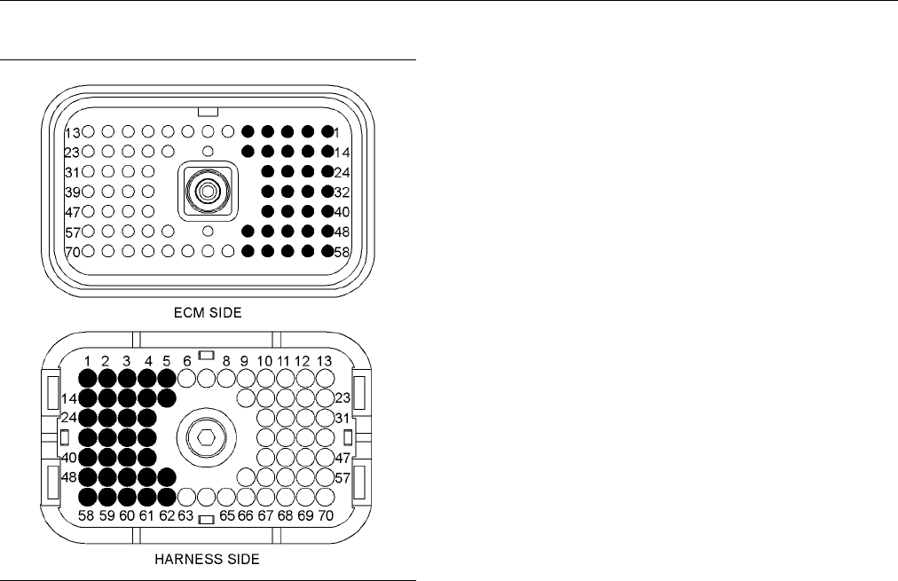
ion 47
P2 terminals that are associated with the injector solenoids
(P2-1) Injector cylinder #1 return
(P2-2) Injector cylinder #1 signal
(P2-3) Injector cylinder #2 return
(P2-4) Injector cylinder #2 signal
(P2-40) Injector cylinder #3 return
(P2-41) Injector cylinder #3 signal
(P2-42) Injector cylinder #4 return
(P2-43) Injector cylinder #4 signal
(P2-14) Injector cylinder #5 return
(P2-15) Injector cylinder #5 signal
(P2-16) Injector cylinder #6 return
(P2-17) Injector cylinder #6 signal
(P2-48) Injector cylinder #7 return
(P2-49) Injector cylinder #7 signal
(P2-50) Injector cylinder #8 return
(P2-51) Injector cylinder #8 signal
(P2-24) Injector cylinder #9 return
(P2-25) Injector cylinder #9 signal
(P2-34) Injector cylinder #10 return
(P2-35) Injector cylinder #10 signal
(P2-58) Injector cylinder #11 return
(P2-59) Injector cylinder #11 signal
(P2-52) Injector cylinder #12 return
(P2-62) Injector cylinder #12 signal
(P2-32) Injector cylinder #13 return
(P2-33) Injector cylinder #13 signal
(P2-1) Injector cylinder #14 return
(P2-60) Injector cylinder #14 signal
(P2-61) Injector cylinder #15 return
(P2-18) Injector cylinder #15 signal
(P2-26) Injector cylinder #16 return
(P2-27) Injector cylinder #16 signal
Test Step 1. Check
for Connector Damage
A. Remove power from the ECM.
B. Thoroughly inspect the ECM connector J2/P2.
Inspect the con
nectors for the right rail and for
the left rail. Refer to the diagnostic functional
test Troubleshooting, “Inspecting Electrical
Connectors” f
or details.
C. Perform a 45 N (10 lb) pull test on each of the
wires in the E
CM connector that are associated
with the circuit.
D. Check the all
en head screw on each ECM
connector for the proper torque. Refer
to Troubleshooting, “Inspecting Electrical
Connectors”
for the correct torque values.
E. Check the harness and the wiring for abrasion
and for pinch
points.
Expected Result:
All connectors, pins, and sockets are completely
coupled and/or inserted, and the harness and wiring
arefreeofc
orrosion, of abrasion and of pinch points.
Results:
•
OK – The connectors and wiring are OK. Proceed
to Test Step 2.
•
Not OK – There is a problem in the connectors
and/or wiring.
Repair: Repair the connectors or wiring and/or
replace the connectors or wiring. Ensure that all of
the seals a
re properly in place and ensure that the
connectors are completely coupled.
Verify tha
t the repair eliminates the problem.
STOP.
Test Step 2. Check for Logged Diagnostic
Codes
A. Connect C
at ET to the service tool connector.
B. Restore power to the ECM.
C. Check for logged diagnostic codes for the injector
solenoids on Cat ET.
Expected Result:
No 1-05 to
16-05 or 1-06 to 16-06 are logged.
Results:
•
OK –No1-05to16-05or1-06to16-06are
logged. Proceed to Test Step 3.
Contents Summary of Caterpillar 3516B and 3516B High Displacement Engines for Caterpillar Built Machines Troubleshooting
- Page 1RENR5622 September 2005 Troubleshooting 3516B and 3516B High Displacement Engines for Caterpillar Built Machines FDB1-Up (Machine) 8WM1-Up (Engine) 7TR1-Up (Engine) For use with 793D Off-Highway Trucks/Tractors�
- Page 2i01658146 Important Safety Information Most accidents that involve product operation, maintenance and repair are caused by failure to observe basic safety rules or precautions. An accident can often be avoided by recognizing potentially hazardous situations before an accident occurs. A person must b
- Page 3RENR5622 3 Table of Contents Table of Contents Diagnostic Functional Tests Analog Sensor (Active) ......................................... 65 Cat Data Link ........................................................ 73 Coolant Flow Switch ............................................. 76 Troubleshootin
- Page 44 RENR5622 Troubleshooting Section Troubleshooting Section Injection timing depends on the following conditions: desired engine rpm and load. The ECM detects the top center of each cylinder. The ECM sends an injection signal at the desired time. Electronic Troubleshooting Cold Cylinder Cutout i02414
- Page 5RENR5622 5 Troubleshooting Section “Multi-Torque” and “Dual Horsepower” Selection This feature permits the use of different torque maps for different transmissions. The feature reduces the number of software part numbers that are required for operation. The feature protects the transmission from exc
- Page 66 RENR5622 Troubleshooting Section g01206901 Illustration 1�
- Page 7RENR5622 7 Troubleshooting Section Typical schematic Engine Wiring Diagram g01206905 Illustration 2 Typical schematic�
- Page 88 RENR5622 Troubleshooting Section Engine Wiring Diagram g01206909 Illustration 3 Typical schematic�
- Page 9RENR5622 9 Troubleshooting Section Location of the 3516B Engine Sensors g01208645 Illustration 4 Front and Left view (1) Turbocharger compressor outlet (5) Left turbocharger compressor inlet (12) Connector for the remote shutdown pressure sensor (boost) pressure sensor (13) Low oil level switch (2)
- Page 1010 RENR5622 Troubleshooting Section Location of the 3516B Engine Sensors g01208648 Illustration 5 Rear and Right view (18) Aftercooler temperature sensor (rear) (22) Crankcase pressure sensor (19) Right exhaust temperature sensor (23) Connector for the engine oil renewal (20) Connector for the waste
- Page 11RENR5622 11 Troubleshooting Section i02319628 Logged codes may not indicate that a repair is needed. The problem may have been temporary. Self-Diagnostics Logged codes may be useful to help troubleshoot intermittent problems. Logged codes can also be SMCS Code: 1901-038 used to review the performanc
- Page 1212 RENR5622 Troubleshooting Section i02414932 Electrical Connectors and Functions SMCS Code: 1408-038 Engine Electronic Control Module (ECM) g01158941 Illustration 6 Connectors for the ECM�
- Page 13RENR5622 13 Troubleshooting Section Machine Connector g01207090 Illustration 7 40 pin machine connector Service Tool Connector for Cat ET g01158896 Illustration 8�
- Page 1414 RENR5622 Troubleshooting Section Sensor Connectors g01207085 Illustration 9 Typical engine connectors i02419684 Electronic Service Tools SMCS Code: 1901-038 Caterpillar Electronic Service Tools are designed to help the service technician: • Obtain data. • Diagnose problems. • Read parameters. • P
- Page 15RENR5622 15 Troubleshooting Section Table 1 • Event codes Required Service Tools • Diagnostic codes Part Description Number • Engine configuration N/A 4 mm Allen Wrench Cat ET can be used by the technician to perform the 6V-2197 Transducer following functions: 7X-1171 Transducer Adapter • Diagnostic
- Page 1616 RENR5622 Troubleshooting Section Connecting Cat ET and the 4. Restore electrical power to the ECM. If Cat ET and Communication Adapter II the communication adapter do not communicate with the Electronic Control Module (ECM), refer to troubleshooting without a diagnostic code Troubleshooting, “Ele
- Page 17RENR5622 17 Troubleshooting Section Table 4 Cross-Reference from “MID-CID-FMI Code” to Functional Test or Procedure “MID-CID-FMI Code” Functional Test or Procedure MID 0036 - CID 0001 - FMI 05 Cylinder #1 Injector open “Injector Solenoids” circuit MID 0036 - CID 0001 - FMI 06 Cylinder #1 Injector sh
- Page 1818 RENR5622 Troubleshooting Section (Table 4, contd) Cross-Reference from “MID-CID-FMI Code” to Functional Test or Procedure “MID-CID-FMI Code” Functional Test or Procedure MID 0036 - CID 0015 - FMI 06 Cylinder #15 Injector short “Injector Solenoids” MID 0036 - CID 0016 - FMI 05 Cylinder #16 Injecto
- Page 19RENR5622 19 Troubleshooting Section (Table 4, contd) Cross-Reference from “MID-CID-FMI Code” to Functional Test or Procedure “MID-CID-FMI Code” Functional Test or Procedure MID 0036 - CID 0275 - FMI 04 Right Turbo Inlet Pressure “Analog Sensor (Active)” short to ground MID 0036 - CID 0276 - FMI 03 L
- Page 2020 RENR5622 Troubleshooting Section (Table 4, contd) Cross-Reference from “MID-CID-FMI Code” to Functional Test or Procedure “MID-CID-FMI Code” Functional Test or Procedure MID 0036 - CID 0829 - FMI 04 Rear Aftercool Temperature “Analog Sensor (Active)” short to ground MID 0036 - CID 1495 - FMI 02 I
- Page 21RENR5622 21 Troubleshooting Section Logged Diagnostic Codes When the ECM generates a diagnostic code, the ECM logs the code in permanent memory. The ECM has an internal diagnostic clock. Each ECM will record the following information when a code is generated: • The hour of the first occurrence of th
- Page 2222 RENR5622 Troubleshooting Section Table 6 Cross-Reference from Event Code to Troubleshooting Procedure Event Code Troubleshooting Procedure E017 High Engine Coolant Temperature Warning “Coolant Temperature Is Too High” E021 High Exhaust Temperature Derate “Exhaust Temperature Is Too High” E035 Los
- Page 23RENR5622 23 Troubleshooting Section • E360-1 Low Oil Pressure Warning • E360-2 Low Oil Pressure Derate • E360-3 Low Oil Pressure Shutdown The definition for a warning, a derate, and a shutdown are defined below: Warning – This condition represents a serious problem with engine operation. However, th
- Page 2424 RENR5622 Troubleshooting Section Troubleshooting Table 7 contains the conditions that are monitored and the default trip points for each condition. Each For basic troubleshooting of the engine, perform the condition has an associated parameter. The settings following steps in order to diagnose a
- Page 25RENR5622 25 Troubleshooting Section Table 7 Trip Points for the Monitoring System Delay Time in Seconds Trip Point Condition Action Default Min Max Default Min Max Default State E017 High Engine Coolant 102 °C Warning N/A N/A 5 N/A N/A On Temperatur (216 °F) E021 High Exhaust 500 °C 800 °C 750 °C De
- Page 2626 RENR5622 Troubleshooting Section g01210600 Illustration 13 Low oil pressure map Default Conditions for the Monitoring System Table 8 contains the default conditions that cause an event code to be generated. Table 8 also contains a column that describes the system response when the conditions indi
- Page 27RENR5622 27 Troubleshooting Section (Table 8, contd) Default Conditions and System Response Event Code Conditions which Generate this Code System Response E072 Oil Level Low Mark The oil level switch opens. The code is active and the code is logged. E073 Oil Filter Differential Pressure The oil filt
- Page 2828 RENR5622 Troubleshooting Section Programming Parameters Note: The old interlock code and the new interlock code are required to change the interlock code on a used Electronic Control Module (ECM). i01951720 The Cat ET screen for factory passwords will display Programming Parameters the following
- Page 29RENR5622 29 Troubleshooting Section • Full load setting • Full torque setting The following information is required to obtain Caterpillar Factory Passwords: • Caterpillar Dealer Code • Name • Address • Phone Number The following information is required to obtain factory passwords. • Engine hours Not
- Page 3030 RENR5622 Troubleshooting Section If you do not have the flash file, use the “Flash File i02416716 Search” tool on the Service Technician Workbench (STW) to obtain the flash file for your engine. System Configuration Alternatively, use the “Service Software Files” feature Parameters on SIS Web to
- Page 31RENR5622 31 Troubleshooting Section Table 11 Diagnostic Codes Table Description Conditions which Generate this Code System Response MID 0036 - CID 0268 - FMI 02 Check The engine’s Electronic Control Module The code is active. Programmable Parameters (ECM) detects that one or more of the The ECM may
- Page 3232 RENR5622 Troubleshooting Section Parameter Table Table 12 System Configuration Parameters Parameter Default Range Password “Engine Serial Number” 00000000 8 alphanumeric characters Yes “Equipment ID” 00000000000000000 17 alphanumeric characters No “Full Load Setting (FLS)” Not Programmed −128 to
- Page 33RENR5622 33 Troubleshooting Section Table 13 Injector Trim Code Injector Default Range Password “Inj #1 e-trim” 0000 4 numeric characters No “Inj #2 e-trim” 0000 4 numeric characters No “Inj #3 e-trim” 0000 4 numeric characters No “Inj #4 e-trim” 0000 4 numeric characters No “Inj #5 e-trim” 0000 4 n
- Page 3434 RENR5622 Troubleshooting Section i02418891 b. Print the parameters from the “Configuration” screen on Cat ET. If a printer is unavailable, Replacing the ECM record all of the parameters. Record any logged diagnostic codes and logged event SMCS Code: 1901-038 codes for your records. Record the inj
- Page 35RENR5622 35 Troubleshooting Section 3. Install the replacement ECM. a. Use the old mounting hardware to install the replacement ECM. The mounting hardware should be free of damage. b. Reconnect the fuel lines (if equipped). c. Ensure that the ECM mounting hardware is installed correctly. The fuel li
- Page 3636 RENR5622 Troubleshooting Section Troubleshooting without a • Determine if the logged diagnostic codes correlate to probable causes. Diagnostic Code • Determine if the logged diagnostic codes occur at the same time as the symptoms. i02319685 Symptoms • Determine if the logged diagnostic codes are
- Page 37RENR5622 37 Troubleshooting Section i02418528 Boost Pressure Above Normal SMCS Code: 1000-035; 1901-038 Use this procedure in order to troubleshoot a high boost pressure or the following event code. Refer to Troubleshooting, “Event Code List” for information on specific trip points for the event cod
- Page 3838 RENR5622 Troubleshooting Section Table 17 Event Code Description Conditions which Generate this Code System Response E093 Boost Pressure Below Normal The actual boost pressure is below the The code is logged and the code is desired boost pressure. active. Probable Causes c. Check fuel quality. In
- Page 39RENR5622 39 Troubleshooting Section Intermittent Sensor Problem Flash File Check for any recently logged diagnostic codes. Verify that the correct flash file has been installed. Check the connectors and wiring for any signs of damage. Refer to the diagnostic functional test Throttle Signal Troublesh
- Page 4040 RENR5622 Troubleshooting Section Injectors Cracked Cylinder Liner Use Cat ET to determine if any active diagnostic Check the cylinder liner for cracks. Use a borescope codes are present for the injector solenoids. Perform to check the cylinder liner. the “Injector Solenoid Test”. Observe that the
- Page 41RENR5622 41 Troubleshooting Section Table 18 Event Code Description Conditions which Generate this Code System Response E038 Low Engine Coolant Temperature The coolant temperature is below the The code is active and the code is Warning trip point. logged. Probable Causes • Faulty water temperature r
- Page 4242 RENR5622 Troubleshooting Section • Faulty radiator cooling fan (if equipped) Faulty Jacket Water Coolant Pump • Faulty pressure relief valve Inspect the impeller vanes at the jacket water pump for damage and/or for erosion. Repair impeller vanes • Faulty temperature regulator and/or replace the i
- Page 43RENR5622 43 Troubleshooting Section Table 20 Event Code Description Conditions which Generate this Code System Response E101 High Crankcase Pressure Engine crankcase pressure is above The code is active and the code is Warning the trip point for high pressure. logged. Probable Causes • Reason code •
- Page 4444 RENR5622 Troubleshooting Section 3. Refer to the diagnostic functional test Electrical Connectors Troubleshooting, “Cat Data Link”. Check for correct installation of the J1/P1 and J2/P2 ECM connectors and of the service tool connector. i02304646 Refer to Troubleshooting, “Inspecting Electrical El
- Page 45RENR5622 45 Troubleshooting Section Note: The new ECM does not have a flash file. Starting Aids The engine will not start and the engine will not communicate with Cat ET until the flash file has 1. If cold ambient conditions exist, check operation been installed. Refer to Troubleshooting, “Flash of
- Page 4646 RENR5622 Troubleshooting Section 3. Check the fuel tank for foreign objects which may Recommended Actions block the fuel supply. Incorrect Engine Oil NOTICE Do not crank the engine continuously for more than Use engine oil that is recommended and change the 30 seconds. Allow the starting motor to
- Page 47RENR5622 47 Troubleshooting Section i02385587 Unit Injectors Engine Misfires, Runs Rough 1. Use Cat ET to determine if there are any active or Is Unstable diagnostic codes for the unit injectors. SMCS Code: 1000-038; 1901-038 2. Perform the “Injector Solenoid Test” on Cat ET in order to determine if
- Page 4848 RENR5622 Troubleshooting Section 3. Check the air inlet and exhaust system for i02418648 restrictions and/or leaks. Refer to the Systems Operation/Testing and Adjusting for information on Engine Overspeed the air inlet and exhaust system. SMCS Code: 1000-038; 1901-038 i02424547 Use this procedure
- Page 49RENR5622 49 Troubleshooting Section Table 21 Event Code Description Conditions which Generate this Code System Response E190 Engine Overspeed Warning The engine rpm is above the trip point The code is active and the code is for overspeed. logged. Probable Causes 2. Perform the “Injector Solenoid Tes
- Page 5050 RENR5622 Troubleshooting Section 6. Check the fuel pressure after the fuel filter while • Internal engine problem the engine is being cranked. Refer to the Systems Operation/Testing and Adjusting manual for the correct pressure values. If the fuel pressure is low, Recommended Actions replace the
- Page 51RENR5622 51 Troubleshooting Section Transmission or Engine Accessories (if • Oil level applicable) • Engine oil cooler 1. If the engine’s application has a transmission neutral switch, test the operation of the • Turbocharger transmission neutral switch. Ensure that the machine is in neutral gear be
- Page 5252 RENR5622 Troubleshooting Section • Fuel injector Atmospheric Pressure Sensor • Turbocharger 1. Check the atmospheric pressure sensor for dirt and/or for debris. Remove the dirt and/or the • Atmospheric pressure sensor debris. The atmospheric pressure should be between 50 kPa (7.2 psi) and 100 kPa
- Page 53RENR5622 53 Troubleshooting Section Valve Adjustment 2. Compare the coolant temperature from Cat ET to the coolant temperature that is obtained from the Check the valve adjustment. Refer to the Systems 6V-9130 Temperature Adapter (MULTIMETER). Operation/Testing and Adjusting manual for more informat
- Page 5454 RENR5622 Troubleshooting Section Component Wear Check the engine for the following problems: Excessive valve wear, piston wear, ring wear, liner wear, and reduced compression pressure. Cooling System Check for proper operation of the jacket water heater. Repair the jacket water heater or replace
- Page 55RENR5622 55 Troubleshooting Section i02119587 i01405833 Fuel Dilution of Engine Oil Fuel in Cooling System SMCS Code: 1300-038; 1901-038 SMCS Code: 1350-038; 1901-038 Probable Causes Probable Causes • Leaking seals on the case of the unit injector or on • Internal cylinder head the barrel of the uni
- Page 5656 RENR5622 Troubleshooting Section Table 23 Event Code Description Default Conditions which Generate System Response this Code E272 Air Filter Restriction Warning The inlet air restriction is above the trip The code is active and the code is point. logged. Probable Causes Engine Shutdown Switch (if
- Page 57RENR5622 57 Troubleshooting Section Fuel Supply • Derates 1. Check the fuel lines for the following problems: • Throttle signal restrictions, collapsed lines, and pinched lines. If problems are found with the fuel lines, repair the • Power supply for the Electronic Control Module lines and/or replac
- Page 5858 RENR5622 Troubleshooting Section Check for an air filter restriction indicator. Replace 5. Check the fuel pressure after the fuel filter plugged air filters and/or clean filters. Repair any while the engine is being cranked. Refer to leaks. the Systems Operation/Testing and Adjusting manual for t
- Page 59RENR5622 59 Troubleshooting Section Table 24 Event Code Description Conditions which Generate this Code System Response E072 Oil Level Low Mark The oil level switch opens. The code is active and the code is logged. E073 Oil Filter Differential Pressure The oil filter differential pressure is High gr
- Page 6060 RENR5622 Troubleshooting Section Recommended Actions Fuel Ratio Control Limit (FRC) Cold Mode Operation and Cold Cylinder Operate the engine under full load. Use Cat ET in order to monitor the following values: turbocharger Cutout compressor outlet pressure, fuel position, rated fuel position, an
- Page 61RENR5622 61 Troubleshooting Section i02304760 • Engine speed/timing sensor Mechanical Noise (Knock) in • Electrical connectors Engine • Injector SMCS Code: 1000-038; 1901-038 • Not enough lubrication Probable Causes • Too much valve lash • Faulty accessory • Damage to valve train components • Damage
- Page 6262 RENR5622 Troubleshooting Section Valve Lash Electrical Connectors Check the valve lash. Refer to the diagnostic Check for the correct installation of the connectors procedure Troubleshooting, “Too Much Valve Lash”. for the Electronic Control Module (ECM) J1/P1 and/or J2/P2. Check for the correct
- Page 63RENR5622 63 Troubleshooting Section 5. Check the fuel pressure after the fuel filter Recommended Actions while the engine is being cranked. Refer to the Systems Operation/Testing and Adjusting Rocker Arm manual for the correct pressure values. If the fuel pressure is low, replace the fuel filters. I
- Page 6464 RENR5622 Troubleshooting Section Valve Seats i02304892 Check the valve seats for signs of wear. If there is Valve Rotocoil or Spring Lock too much wear, install new valve seats. Adjust the Is Free valve lash. SMCS Code: 1109-038 i02304874 Probable Causes Too Much Vibration SMCS Code: 1000-038; 19
- Page 65RENR5622 65 Troubleshooting Section Diagnostic Functional Tests i02408931 Analog Sensor (Active) SMCS Code: 5574-038 System Operation Description: Use this procedure to troubleshoot the electrical system if a problem is suspected with the sensors or if any one of the diagnostic codes in Table 25 is
- Page 6666 RENR5622 Troubleshooting Section (Table 25, contd) Diagnostic Codes Table Description Conditions which Generate this Code System Response MID 0036 - CID 0275 - FMI 03 Right The ECM detects signal voltage that is The code is logged. Turbo Inlet Pressure open/short to +batt above normal for one sec
- Page 67RENR5622 67 Troubleshooting Section • Coolant temperature sensor • Crankcase pressure sensor • Filtered engine oil pressure sensor • Left turbocharger inlet pressure sensor • Right turbocharger inlet pressure sensor • Turbocharger outlet pressure sensor • Unfiltered engine oil pressure sensor The su
- Page 6868 RENR5622 Troubleshooting Section g01203777 Illustration 14 Typical schematic�
- Page 69RENR5622 69 Troubleshooting Section g01208832 g01208831 Illustration 15 Illustration 16 Front and Left view Rear and Right view (1) Turbocharger compressor outlet pressure sensor (boost) (9) Aftercooler temperature sensor (rear) (2) Aftercooler temperature sensor (front) (10) Crankcase pressure sens
- Page 7070 RENR5622 Troubleshooting Section g01203763 g01203760 Illustration 17 Illustration 18 P1 ECM connector P2 ECM connector (P1-1) Aftercooler temperature sensor (front) (P2-36) Turbocharger outlet pressure sensor (P1-2) 5 V sensor supply (P2-37) Atmospheric sensor (P1-3) Sensor return (P2-38) Left tu
- Page 71RENR5622 71 Troubleshooting Section B. Restore electrical power to the ECM. Results: C. Monitor the diagnostic codes on Cat ET. Check • OK – No intermittent problems were found. The and record any diagnostic codes. harness and connectors appear to be OK. If a diagnostic code is still active, proceed
- Page 7272 RENR5622 Troubleshooting Section F. Remove electrical power from the ECM. Repair: Temporarily connect a new sensor to the harness, but do not install the new sensor in the Expected Result: engine. Verify that there are no active diagnostic codes for the sensor. If there are no active A 04 diagnos
- Page 73RENR5622 73 Troubleshooting Section Expected Result: Results: A 03 diagnostic code is active when the sensor • OK – The supply voltage is 5.0 ± 0.2 VDC. The signal wire is removed from the ECM connector. A supply voltage at the ECM is correct. There is a 04 diagnostic code is active when the signal
- Page 7474 RENR5622 Troubleshooting Section Table 26 Diagnostic Codes Table Description Conditions which Generate this Code System Response MID 0036 - CID 0296 - FMI 09 Unable to The engine’s Electronic Control Module The code is logged. communicate with Transmission ECM (ECM) detects a failure in the Cat D
- Page 75RENR5622 75 Troubleshooting Section g01203833 Illustration 20 Schematic Test Step 1. Inspect the Electrical Connectors and the Wiring A. Remove power from the ECM. B. Thoroughly inspect the ECM connectors J1/P1 and J2/P2. Inspect all of the connectors to other modules on the Cat Data Link. Refer to
- Page 7676 RENR5622 Troubleshooting Section • Not OK – The connectors and/or wiring are not C. Measure the resistance at the connectors of the OK. other control modules. Repair: Repair the connectors or wiring and/or Expected Result: replace the connectors or wiring. Ensure that all of the seals are properl
- Page 77RENR5622 77 Troubleshooting Section Table 27 Event Code Description Default Conditions which Generate System Response this Code E035 Loss of Coolant Flow Warning The coolant flow switch opens. The code is active and the code is logged. The coolant flow switch is used to determine if there is suffici
- Page 7878 RENR5622 Troubleshooting Section g01147985 g01147988 Illustration 24 Illustration 25 P1 ECM connector P2 ECM connector (P1-30) Coolant flow (P2-54) Digital return Test Step 1. Check the Coolant Level A. Check the coolant level. Refer to the Operation and Maintenance Manual for information on chec
- Page 79RENR5622 79 Troubleshooting Section Test Step 2. Inspect Electrical Connectors Expected Result: and Wiring Cat ET indicates “NO FLOW” while the engine is not A. Remove electrical power from the engine ECM. running. Cat ET indicates “FLOW” while the engine is running. B. Thoroughly inspect the J1/P1
- Page 8080 RENR5622 Troubleshooting Section Test Step 5. Check the Coolant Flow C. Reconnect the J1/P1 ECM connector. Switch D. Use a suitable piece of wire to short the wire jumper in P1-30 to engine ground. Pressurized System: Hot coolant can cause seri- E. Turn the keyswitch to the ON position. ous burns
- Page 81RENR5622 81 Troubleshooting Section Table 28 Diagnostic Codes Table Description Conditions which Generate this Code System Response MID 0036 - CID 0168 - FMI 01 System The battery supply voltage is less than The code is logged if the engine is Voltage Low 9 VDC for two seconds. running. The engine’s
- Page 8282 RENR5622 Troubleshooting Section g01203933 Illustration 26 Typical schematic�
- Page 83RENR5622 83 Troubleshooting Section Results: • OK – The harness and wiring are OK. Proceed to Test Step 2. • Not OK – There is a problem in the connectors and/or wiring. Repair: Repair the connectors or wiring and/or replace the connectors or wiring. Ensure that all of the seals are properly in plac
- Page 8484 RENR5622 Troubleshooting Section Repair: If an intermittent condition is suspected, • Not OK – Voltage is not present on terminal R at refer to Troubleshooting, “Inspecting Electrical the keyswitch. Connectors”. Repair: If voltage is present on terminal B of the STOP. keyswitch but not present on
- Page 85RENR5622 85 Troubleshooting Section Repair: Verify that the “Alternator Breaker” is not tripped. Repair the wiring and/or connectors between the main power relay and the “Alternator Breaker”. Repair the wiring and/or connectors between the “Alternator Breaker” and the battery. STOP. • Not OK – The v
- Page 8686 RENR5622 Troubleshooting Section g01208732 Illustration 28 Left side view (1) Low oil level switch g01203953 Illustration 29 Schematic�
- Page 87RENR5622 87 Troubleshooting Section Test Step 1. Inspect Electrical Connectors and Wiring A. Turn the keyswitch to the OFF position. B. Thoroughly inspect the ECM connectors J1/P1 and J2/P2. Inspect the connector for the low oil level switch. Refer to Troubleshooting, “Inspecting Electrical Connecto
- Page 8888 RENR5622 Troubleshooting Section Repair: Add oil to the engine. Results: STOP. • OK – Cat ET indicates “OK”, when the wire short is in place. Cat ET indicates “LOW”, when the wire Test Step 3. Check the Engine Oil Level short is removed. Cat ET recognized the input from on Caterpillar Electronic
- Page 89RENR5622 89 Troubleshooting Section Expected Result: Cat ET indicates that the “Engine Oil Level” is “OK” when the wire short is installed. Cat ET indicates that the “Engine Oil Level” is “LOW” when the wire short is removed. Results: • OK – Cat ET indicates that the “Engine Oil Level” is “OK” when
- Page 9090 RENR5622 Troubleshooting Section Use this procedure to troubleshoot any suspect problems with the system for the engine oil renewal solenoid. This procedure covers the following diagnostic codes: • 2271-05 Engine Oil Renewal System Actuation Solenoid current low • 2271-06 Engine Oil Renewal Syste
- Page 91RENR5622 91 Troubleshooting Section Results: • OK – The connectors and wiring are OK. Proceed to Test Step 2. • Not OK – There is a problem in the connectors and/or wiring. Repair: Repair the connectors or wiring and/or replace the connectors or wiring. Ensure that all of the seals are properly in p
- Page 9292 RENR5622 Troubleshooting Section F. Measure the voltage between terminal 1 and Repair: Replace the ECM. Refer to terminal 2 at the solenoid connector. Troubleshooting, “Replacing the ECM”. Expected Result: STOP. The voltage is approximately 24 VDC. i02409685 Results: Engine Speed/Timing Sensor •
- Page 93RENR5622 93 Troubleshooting Section Table 32 Event Code Description Conditions which Generate this Code System Response MID 0036 - CID 0190 - FMI 08 Engine The engine speed is greater than zero The engine speed is set to zero rpm. Speed signal abnormal rpm and the pattern from the timing ring The co
- Page 9494 RENR5622 Troubleshooting Section g01204148 Illustration 35 Schematic B. Thoroughly inspect the ECM connectors J1/P1 and J2/P2. Inspect all of the other connectors for the circuit. Refer to Troubleshooting, “Inspecting Electrical Connectors” for details. C. Perform a 45 N (10 lb) pull test on each
- Page 95RENR5622 95 Troubleshooting Section Test Step 2. Check for a “LOGGED” D. Measure the voltage between the sensor signal Diagnostic Code wire and terminal B of the sensor connector. Crank the engine and measure the voltage between the A. Connect Caterpillar Electronic Technician (ET) to sensor signal
- Page 9696 RENR5622 Troubleshooting Section Expected Result: Results: The voltage measures less than 3 VDC or more than • OK – The supply voltage is 12 ± 1.0 VDC. There is 9 VDC when the keyswitch is in the ON position an open circuit or a short circuit between the ECM and the engine is not cranking. While
- Page 97RENR5622 97 Troubleshooting Section Table 33 Diagnostic Codes Table Description Conditions which Generate this Code System Response MID 0036 - CID 0545 - FMI 05 Ether The engine’s Electronic Control Module The code is logged. Start Relay open/short to +batt (ECM) detects an open circuit and/or a Eth
- Page 9898 RENR5622 Troubleshooting Section The device driver in the second circuit provides a return path to the ECM from the coil of the ether hold relay. The other side of the coil is connected to the +Battery. The ECM monitors current flow in the circuit in order to determine if there is a problem in th
- Page 99RENR5622 99 Troubleshooting Section g01149844 Illustration 38 Terminal locations for the ether start relay and for the ether hold relay g01204311 Illustration 40 P2 ECM connector (P2-10) Ether hold relay (P2-20) Ether request (P2-31) Ether start relay Test Step 1. Inspect Electrical Connectors and W
- Page 100100 RENR5622 Troubleshooting Section Results: Expected Result: • OK – The harness and wiring are OK. Proceed The parameter for the starting aid switch displays to Test Step 2. “ON” while the starting aid switch is toggled. The parameter for the starting aid switch displays “OFF” • Not OK – There is
- Page 101RENR5622 101 Troubleshooting Section D. Select the “Diagnostic Tests” on Cat ET. E. Select the “Override Parameters” screen on Cat ET. NOTICE Do not allow the ether injection system to be on for F. Activate the ether override. more than two minutes. Damage to the ether solenoid may occur. G. Monitor
- Page 102102 RENR5622 Troubleshooting Section Repair: The ECM detected the open circuit at b. Turn the keyswitch to the ON position. the relay connector. The problem must be in the connector for the suspect relay or the problem c. Select the “Diagnostic Tests” on Cat ET. must be in the relay assembly. NOTICE
- Page 103RENR5622 103 Troubleshooting Section • Not OK – One of the following conditions exists: • Not OK - 24 VDC – The voltage did not measure The 05 diagnostic code is not active when the 24 ± 3 VDC for the first two seconds of injection. wires or wire from the suspect relay are open at Verify that wire 2
- Page 104104 RENR5622 Troubleshooting Section Repair: Verify that the breaker for the starting aid C. Connect the positive lead of the multimeter to is not tripped. Check the wiring between the relay terminal 2 and the negative lead to terminal 1 of connectors and the battery for an open circuit or the resis
- Page 105RENR5622 105 Troubleshooting Section E. Obtain a suitable piece of wire. Short the wires c. Observe the parameter for the starting aid from the starting aid switch together at the starting switch on Cat ET. aid switch. H. Check the operation of the ECM by creating a F. Observe the parameter for the
- Page 106106 RENR5622 Troubleshooting Section i02410957 Fuel Filter Differential Pressure Switch SMCS Code: 1261-038-ZS System Operation Description: Use this procedure in order to troubleshoot a problem with the circuit for the fuel filter differential pressure switch or use this procedure if the following
- Page 107RENR5622 107 Troubleshooting Section g01204990 Illustration 42 Schematic Results: • OK – The E095 event code is no longer active. STOP. • Not OK – The fuel filter element was replaced. The E095 event code is still active. Proceed to Test Step 2. Test Step 2. Inspect Electrical Connectors and Wiring
- Page 108108 RENR5622 Troubleshooting Section • Not OK – There is a problem in the connectors B. Disconnect the J1/P1 ECM connector. and/or wiring. C. Install a jumper wire with Deutsch sockets on each Repair: Repair the connectors or wiring and/or end into the socket for the signal wire of the fuel replace
- Page 109RENR5622 109 Troubleshooting Section Repair: Replace the ECM. Refer to Troubleshooting, “Replacing the ECM”. Verify that the problem is resolved. STOP. i02411006 Ground Level Shutdown Switch SMCS Code: 1901-038 System Operation Description: Use this procedure in order to troubleshoot a problem with
- Page 110110 RENR5622 Troubleshooting Section g01205050 Illustration 44 Schematic C. Perform a 45 N (10 lb) pull test on each of the wires in the ECM connector that are associated with the circuit. D. Check the ECM connector (allen head screw) for the proper torque. Refer to Troubleshooting, “Inspecting Elec
- Page 111RENR5622 111 Troubleshooting Section C. Operate the ground level shutdown switch. I. Observe the status of the ground level shutdown Observe the status for the ground level shutdown switch on Cat ET. switch on Cat ET. J. Turn the keyswitch to the OFF position. Expected Result: K. Remove the wire sho
- Page 112112 RENR5622 Troubleshooting Section Note: The digital return will no longer be connected to i02411251 the other sensors and switches. Additional diagnostic codes will be generated from the ECM. Clear the Injector Solenoids codes after you complete this test. SMCS Code: 1290-038-JV F. Observe the st
- Page 113RENR5622 113 Troubleshooting Section Table 36 Diagnostic Codes Table Description Conditions which Generate this Code System Response MID 0036 - CID 0001 - FMI 05 Cylinder The engine’s Electronic Control Module The code is logged. #1 Injector open circuit (ECM) detects an open circuit. The ECM contin
- Page 114114 RENR5622 Troubleshooting Section (Table 36, contd) Diagnostic Codes Table Description Conditions which Generate this Code System Response MID 0036 - CID 0007 - FMI 05 Cylinder The engine’s ECM detects an open The code is logged. #7 Injector open circuit circuit. The ECM continues to fire the inj
- Page 115RENR5622 115 Troubleshooting Section (Table 36, contd) Diagnostic Codes Table Description Conditions which Generate this Code System Response MID 0036 - CID 0012 - FMI 06 Cylinder The ECM detects a short circuit. The code is logged. #12 Injector short The ECM will disable the solenoid circuit. The E
- Page 116116 RENR5622 Troubleshooting Section When an injector is replaced, program the new injector code into the ECM. If the ECM is replaced, all sixteen injector codes must be programmed into the new ECM. The injector codes are a four digit number. Refer to Troubleshooting, “System Configuration Parameter
- Page 117RENR5622 117 Troubleshooting Section g01205298 Illustration 46 Typical schematic�
- Page 118118 RENR5622 Troubleshooting Section B. Thoroughly inspect the ECM connector J2/P2. Inspect the connectors for the right rail and for the left rail. Refer to the diagnostic functional test Troubleshooting, “Inspecting Electrical Connectors” for details. C. Perform a 45 N (10 lb) pull test on each of
- Page 119RENR5622 119 Troubleshooting Section • Not OK – A 1-05 to 16-05 is logged. Proceed to Test Step 4. Check the Harness between Test Step 4. the ECM and the Injector Connectors for an Open Circuit • Not OK – A 1-06 to 16-06 is logged. Proceed to Test Step 5. Test Step 3. Perform the “Cylinder Cutout Te
- Page 120120 RENR5622 Troubleshooting Section Test Step 5. Check the Harness between a. Disconnect the appropriate suspect injector the ECM and the Connectors for the wire from the P2 ECM connector. Remove the Injector for a Short Circuit signal wire for the suspect injector(s) from the ECM connector. b. Ins
- Page 121RENR5622 121 Troubleshooting Section Expected Result: Repair: The problem may be intermittent. If the problem is intermittent, refer to the diagnostic Cat ET displays “Short” when the wire jumper is functional test Troubleshooting, “Inspecting shorted to engine ground. Cat ET displays “Open” Electri
- Page 122122 RENR5622 Troubleshooting Section The connection of any electrical equipment and the disconnection of any electrical equipment may cause an explosion hazard which may result in in- jury or death. Do not connect any electrical equip- ment or disconnect any electrical equipment in an explosive atmo
- Page 123RENR5622 123 Troubleshooting Section Expected Result: The harness wiring, connectors, and seals are in good condition. There is no evidence of moisture in the connectors. Results: • OK – The harness wiring, connectors, and seals are in good condition. Proceed to Test Step 2. • Not OK – A problem has
- Page 124124 RENR5622 Troubleshooting Section Results: A. Ensure that the locking wedge for the connector is installed properly. Terminals cannot be retained • OK – The harness is OK. Proceed to Test Step 3. inside the connector if the locking wedge is not installed properly. • Not OK – There is damage to th
- Page 125RENR5622 125 Troubleshooting Section Expected Result: The sockets provide good retention for the new pin. Results: • OK – The terminals are OK. Proceed to Test Step 6. • Not OK – Terminals are damaged. Repair: Use the 1U-5804 Crimp Tool to replace the damaged terminals. Verify that the repair elimin
- Page 126126 RENR5622 Troubleshooting Section Expected Result: No intermittent problems were indicated during the “Wiggle Test”. Results: • OK – No intermittent problems were found. The harness and connectors appear to be OK. If you were sent from another procedure, return to the procedure and continue testi
- Page 127RENR5622 127 Troubleshooting Section Table 37 Diagnostic Codes Table Description Conditions which Generate this Code System Response E098 Engine Prelube Override The engine has started without The code is logged. completing the engine prelubrication. MID 0036 - CID 0338 - FMI 05 Pre-lube The engine’
- Page 128128 RENR5622 Troubleshooting Section g01205415 Illustration 58 Schematic�
- Page 129RENR5622 129 Troubleshooting Section g01149844 Illustration 61 Terminal locations of the prelube relay Test Step 1. Inspect Electrical Connectors and Wiring Illustration 59 g01205422 A. Turn the keyswitch to the OFF position. P1 ECM connector B. Thoroughly inspect the ECM connectors. (P1-51) Digital
- Page 130130 RENR5622 Troubleshooting Section Verify that the repair eliminates the problem. Expected Result: STOP. A 05 diagnostic code is now active for the prelube relay. Test Step 2. Check for Active Diagnostic Codes Results: A. Connect Cat ET to the service tool connector. • OK – A 06 diagnostic code wa
- Page 131RENR5622 131 Troubleshooting Section Results: Note: Wait at least 30 seconds so that any codes may become active. • OK – A 06 diagnostic code is active when the jumper wire is installed. A 05 diagnostic code f. Turn the keyswitch to the OFF position. is active when the jumper wire is removed. The en
- Page 132132 RENR5622 Troubleshooting Section Test Step 6. Check the Voltage to the Coil Test Step 7. Check the Voltage at the of the Prelube Switch Prelube Motor A. Disconnect wire 337-WH from the coil of the A. Disconnect the wire to the prelube motor from the prelube switch. prelube switch at the prelube
- Page 133RENR5622 133 Troubleshooting Section Test Step 8. Check the Operation of the Prelubrication Motor A. Turn the keyswitch to the OFF position. B. Connect one side of a suitable piece of 10 AWG wire to the +Battery terminal. C. For one second, connect the other end of the wire to the positive terminal
- Page 134134 RENR5622 Troubleshooting Section Table 38 Diagnostic Codes Table Description Conditions which Generate this Code System Response MID 0036 - CID 0827 - FMI 08 Left The engine’s Electronic Control Module The code is logged. Exhaust Temperature signal abnormal (ECM) detects a sensor frequency that
- Page 135RENR5622 135 Troubleshooting Section g01208743 Illustration 62 Sensor locations (1) Left exhaust temperature sensor (2) Right exhaust temperature sensor g01205563 Illustration 63 Typical schematic�
- Page 136136 RENR5622 Troubleshooting Section g01205567 g01205569 Illustration 64 Illustration 65 P1 ECM connector P2 ECM connector (P1-4) 8 V supply (P2-55) Digital return (P1-11) Left exhaust temperature (P1-12) Right exhaust temperature (P1-60) Digital return g01094844 Illustration 66 Sensor connector (Pi
- Page 137RENR5622 137 Troubleshooting Section Note: Wait at least 30 seconds in order for the • Not OK – At least one intermittent problem was diagnostic codes to become active. indicated. C. Determine if a diagnostic code has occurred Repair: Repair the harness or the connector. Refer several times. to the
- Page 138138 RENR5622 Troubleshooting Section Repair: Repair the connectors or wiring and/or B. Remove the suspect signal wire for the sensor replace the connectors or wiring. from ECM connector P1. Refer to Illustration 63 for the terminal locations for the ECM connector. STOP. C. Restore power to the ECM.
- Page 139RENR5622 139 Troubleshooting Section Table 39 Diagnostic Codes Table Description Conditions which Generate this Code System Response MID 0036 - CID 0262 - FMI 03 5 Volt The analog sensor supply voltage is The code is logged. Sensor DC Power Supply short to +batt above normal for two seconds. All sen
- Page 140140 RENR5622 Troubleshooting Section g01203777 Illustration 67 Typical 5 V supply�
- Page 141RENR5622 141 Troubleshooting Section g01205563 Illustration 68 Typical 8 V supply g01206359 g01206347 Illustration 69 Illustration 70 P1 ECM connector P2 ECM connector (P1-1) Aftercooler temperature sensor (front) (P2-36) Turbocharger outlet pressure sensor (P1-2) 5 V sensor supply (P2-37) Atmospher
- Page 142142 RENR5622 Troubleshooting Section Repair: Repair the connectors or wiring and/or replace the connectors or wiring. Ensure that all of the seals are properly in place and ensure that the connectors are completely coupled. Verify that the repair eliminates the problem. STOP. Test Step 2. Check for
- Page 143RENR5622 143 Troubleshooting Section Note: Wait at least 30 seconds in order for the D. Remove the wires from terminal locations P2-18 diagnostic codes to become active. (5 V sensor supply) and P2-35 (sensor return). Install a jumper wire into each of these terminal a. Disconnect the following senso
- Page 144144 RENR5622 Troubleshooting Section 2. Repair the wiring and/or the connector. Replace B. Fabricate two jumper wires that are long enough parts, if necessary. Verify that the problem is to be used to measure the supply voltage at the resolved. ECM connectors. Crimp connector sockets to one end of e
- Page 145RENR5622 145 Troubleshooting Section 2. Repair the wiring and/or the connector. Replace parts, if necessary. Verify that the problem is resolved. STOP. • Not OK – The voltage measurement is not 8.0 ± 0.4 VDC. Repair: Replace the ECM. Refer to Troubleshooting, “Replacing the ECM”. STOP. i02413879 Thr
- Page 146146 RENR5622 Troubleshooting Section g01206563 Illustration 72 Typical schematic g01151263 g01206568 Illustration 73 Illustration 74 P1 ECM connector Machine connector (P1-4) +8 V digital supply (Terminal 8) +8 V digital supply (P1-5) Digital return (Terminal 9) Digital return (P1-10) Throttle signa
- Page 147RENR5622 147 Troubleshooting Section Expected Result: • Not OK – The throttle position does not read 0 percent when the throttle pedal is released. The The throttle assembly operates smoothly without throttle position does not increase to 100 percent excessive drag. The throttle assembly returns to
- Page 148148 RENR5622 Troubleshooting Section Results: C. Depress the throttle and release the throttle. • OK – A valid duty cycle is present at the sensor D. Turn the keyswitch to the OFF position. connector. Proceed to Test Step 5. Expected Result: • Not OK – A valid duty cycle is not present at the sensor
- Page 149RENR5622 149 Troubleshooting Section F. Measure the voltage between the jumper wire in P1-4 (8 V sensor supply) and P1-60 (sensor return). G. Remove electrical power from the ECM. Expected Result: Each voltage measurement is 8.0 ± 0.4 VDC. Results: • OK – The voltage measurement is 8.0 ± 0.4 VDC. Th
- Page 150150 RENR5622 Troubleshooting Section g01206647 Illustration 75 Typical schematic g01206650 g01206655 Illustration 76 Illustration 77 P1 ECM Connector Machine Connector (P1-21) User defined shutdown (Terminal 13) User defined shutdown Test Step 1. Inspect Electrical Connectors and Wiring A. Turn the
- Page 151RENR5622 151 Troubleshooting Section C. Perform a 45 N (10 lb) pull test on each of the Test Step 3. Create a Short at the wires in the ECM connector that are associated Connector for the User Defined with the circuit. Shutdown D. Check the allen head screw on each ECM A. Use a jumper wire with a so
- Page 152152 RENR5622 Troubleshooting Section Repair: Repair the connectors and/or wiring or Results: replace the connectors or wiring. • OK – Cat ET indicates “User Shutdown ON” with STOP. the wire short in place. Cat ET indicates “User Shutdown OFF” when the wire short is removed. Test Step 5. Check the Ha
- Page 153RENR5622 153 Troubleshooting Section Table 42 Diagnostic Codes Table Description Conditions which Generate this Code System Response MID 0036 - CID 0526 - FMI 05 Turbo The engine’s Electronic Control Module The code is logged. Wastegate Drive current low (ECM) detects an open circuit and/or a short
- Page 154154 RENR5622 Troubleshooting Section Results: • OK – The connectors and wiring are OK. Proceed to Test Step 2. • Not OK – The connectors and/or wiring need repair. Repair: Repair the connectors or wiring and/or replace the connectors or wiring. STOP. Test Step 2. Check for an “Active” Diagnostic Cod
- Page 155RENR5622 155 Troubleshooting Section Test Step 3. Create an Open at the B. Install a jumper wire between terminal 1 and Connector for the Wastegate Solenoid terminal 2 of the connector for the wastegate solenoid. A. Turn the keyswitch to the OFF position. C. Turn the keyswitch to the ON position. B.
- Page 156156 RENR5622 Troubleshooting Section E. Install the jumper wire(s) into the terminal I. Turn the keyswitch to the OFF position. Reconnect location(s) for the wastegate solenoid at the ECM all wires to the original configuration. connector. Expected Result: F. Connect the ECM connectors. A 05 diagnos
- Page 157RENR5622 157 Troubleshooting Section Calibration Procedures i02415146 Engine Speed/Timing Sensor - Calibrate SMCS Code: 1912-524 System Operation Description: Use this procedure if the diagnostic code in Table 43 is active. Table 43 Diagnostic Codes Table Description Conditions which Generate this C
- Page 158158 RENR5622 Troubleshooting Section Note: Wait at least 15 seconds in order for the Repair: Disconnect the timing calibration probe diagnostic codes to become active. before you exit the “Timing Calibration” screen on Cat ET. Reset the system and check for any Expected Result: diagnostic codes. Onl
- Page 159RENR5622 159 Index Section Index A Electrical Connectors and Functions ..................... 12 Engine Electronic Control Module (ECM) .......... 12 Alternator (Noisy Operation).................................. 36 Machine Connector............................................ 13 Probable Causes ....
- Page 160160 RENR5622 Index Section Exhaust Temperature Is Too High ......................... 54 N Probable Causes ............................................... 54 Recommended Actions...................................... 54 Noise Coming from Cylinder.................................. 61 Probable Causes ..
- Page 161RENR5622 161 Index Section W Wastegate Solenoid ............................................ 152�
- Page 162162 RENR5622 Index Section�
- Page 163RENR5622 163 Index Section�
- Page 164©2005 Caterpillar All Rights Reserved Printed in U.S.A.