Removal Procedure
| Required Tools | |||
| Tool | Part Number | Part Description | Qty |
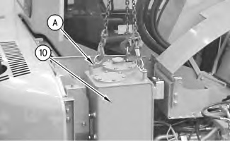
| A | 138-7573 | Link Bracket | 3 |
| B | 6V-9508 | Face Seal Plug | 6 |
| 6V-9829 | Cap As | 6 | |
| 6V-9509 | Face Seal Plug | 1 | |
| 6V-9830 | Cap As | 1 | |
| 6V-9511 | Face Seal Plug | 2 | |
| 6V-9832 | Cap As | 2 | |
Start By:
- Remove the fuel tank. Refer to Disassembly and Assembly, “Fuel Tank – Remove”.
Note: SERVICE DATA: TOOLING (B) WILL NOT BE IDENTIFIED IN PHOTOGRAPHS IN THE REMOVAL OR IN THE INSTALLATION. THIS TOOLING IS SHOWN IN ORDER TO ASSIST THE EXPERIENCED SERVICEMAN.
- Drain the hydraulic oil. Refer to Operation and Maintenance Manual, “Hydraulic System Oil – Change”. The capacity of the hydraulic tank is approximately 55 L (14.5 US gal).
|
Personal injury can result from hydraulic oil pressure and hot oil. Hydraulic oil pressure can remain in the hydraulic system after the engine has been stopped. Serious injury can be caused if this pressure is not released before any service is done on the hydraulic system. Make sure all of the work tools have been lowered to the ground, and the oil is cool before removing any components or lines. Remove the oil filler cap only when the engine is stopped, and the filler cap is cool enough to touch with your bare hand. |
|
|
| NOTICE |
|---|
|
Care must be taken to ensure that fluids are contained during performance of inspection, maintenance, testing, adjusting and repair of the product. Be prepared to collect the fluid with suitable containers before opening any compartment or disassembling any component containing fluids. Refer to Special Publication, NENG2500, “Caterpillar Tools and Shop Products Guide” for tools and supplies suitable to collect and contain fluids on Caterpillar products. Dispose of all fluids according to local regulations and mandates. |
|
|
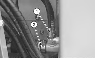
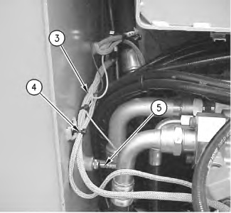
- Disconnect hose (2) .
- Cut cable strap (4). Disconnect harness assembly (5). Position harness assembly (3) out of the way.
|
|
|
|
|
|
| Illustration 2 | g00910804 |