Installation Procedure
|
|
| NOTICE |
|---|
|
Care must be taken to ensure that fluids are contained during performance of inspection, maintenance, testing, adjusting and repair of the product. Be prepared to collect the fluid with suitable containers before opening any compartment or disassembling any component containing fluids. Refer to Special Publication, NENG2500, “Caterpillar Tools and Shop Products Guide” for tools and supplies suitable to collect and contain fluids on Caterpillar products. Dispose of all fluids according to local regulations and mandates. |
|
|
- Make sure that the pin bores in the stick cylinder, the boom and the stick are clean and free of dirt prior to the installation of the stick cylinder.
- Attach a suitable lifting device to the stick cylinder (3). Position the stick cylinder on the boom and the stick. Make sure that the grease fittings in the head end and in the rod end of the stick cylinder are facing away from the boom.
|
|
|
|
|
|
| Illustration 1 | g00543144 |
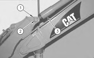
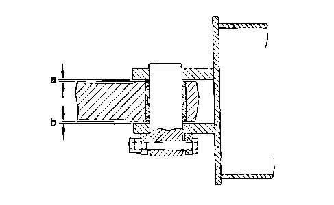
- Slide the stick cylinder to one side until the stick cylinder makes contact with the boom and the stick. Measure the total clearance between the stick cylinder and the stick at the pin bore. The total clearance of Measurement (a) plus Measurement (b) must not be more than 1.0 mm (0.04 inch) at each pin bore. If the total clearance is less than 1.0 mm (0.04 inch), the addition of shims between the stick cylinder and stick will not be required. Apply 5P-0960 Molybdenum Grease on pin (2) and install the pin. Install retaining bolt (1) and the nuts.
- If the total clearance is more than 1.0 mm (0.04 inch), the addition of shims will be required. Install the shims between the stick cylinder and the stick on the same side of the retaining bolt for pin (2). Apply 5P-0960 Molybdenum Grease on pin (2) and install the pin. Install retaining bolt (1) and the nuts.
|
|
|
|
|
|
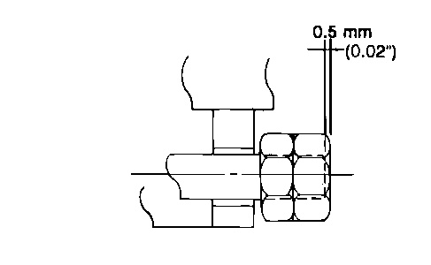
| Illustration 2 | g00545231 |
|
Typical example |
|
- Tighten the outside nut until the nut is 0.5 mm (0.02 inch) beyond the end of the retaining bolt. Tighten the inside nut against the outside nut to a torque of 70 ± 15 N·m (50 ± 10 lb ft).
|
|
|
|
|
|
| Illustration 3 | g00357378 |
- Check the condition of the O-ring seals in the ends of hose assemblies (4) prior to installation. If the seals are damaged, use new parts for replacement. Connect the two hose assemblies to the stick cylinder. Connect hose assembly (7) to the stick cylinder.
|
|
|
|
|
|
| Illustration 4 | g00543186 |
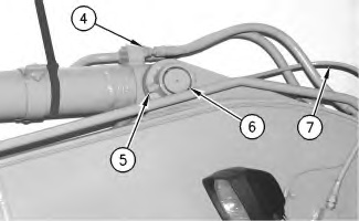
- Slide the stick cylinder to one side until the stick cylinder makes contact with the boom and the stick. Measure the total clearance between the stick cylinder and the boom at the pin bore. The total clearance of Measurement (a) plus Measurement (b) must not be more than 1.0 mm (0.04 inch) at each pin bore. If the total clearance is less than 1.0 mm (0.04 inch), the addition of shims between the stick cylinder and boom will not be required. Apply 5P-0960 Molybdenum Grease on pin (6) and install the pin. Install retaining bolt (5) and the nuts.
- If the total clearance is more than 1.0 mm (0.04 inch), the addition of shims will be required. Install the shims between the stick cylinder and the boom on the side opposite of the retaining bolt for the pin (6). Apply 5P-0960 Molybdenum Grease on pin (6) and install the pin. Install retaining bolt (5) and the nuts.
|
|
|
|
|
|
| Illustration 5 | g00545231 |
|
Typical example |
|
- Tighten the outside nut until the nut is 0.5 mm (0.02 inch) beyond the end of the retaining bolt. Tighten the inside nut against the outside nut to a torque of 100 ± 20 N·m (75 ± 15 lb ft).
|
|
|
|
|
|
| Illustration 6 | g00357378 |
- Fill the hydraulic oil tank with oil. Refer to Operation and Maintenance Manual, SEBU7421, “Hydraulic Oil Level – Check”. Lubricate the pins for the stick cylinder. Refer to Operation and Maintenance Manual, SEBU7421, “Boom and Stick Linkage – Lubricate”.
- Start the machine, and run the machine at low idle speed. Extend the stick cylinder to the halfway position. Retract the cylinder rod. The cylinder should be cycled in this manner for approximately ten cycles in order to remove the air from the hydraulic system. Recheck the oil level in the hydraulic oil tank.