| Required Tools | ||
|---|---|---|
| Part Number | Description | Qty |
| 4J-5477 | O-Ring Seal | 1 |
| 6V-8397 | O-Ring Seal | 1 |
| 6V-8398 | O-Ring Seal | 2 |
| 6V-9509 | Face Seal Plug | 1 |
| 6V-9828 | Cap | 1 |
| 6V-9829 | Cap | 1 |
| 6V-9830 | Cap | 1 |
| Container for Measuring | 1 | |
|
|
| NOTICE |
|---|
|
Care must be taken to ensure that fluids are contained during performance of inspection, maintenance, testing, adjusting and repair of the product. Be prepared to collect the fluid with suitable containers before opening any compartment or disassembling any component containing fluids. Refer to Special Publication, NENG2500, “Caterpillar Tools and Shop Products Guide” for tools and supplies suitable to collect and contain fluids on Caterpillar products. Dispose of all fluids according to local regulations and mandates. |
|
|
- Stop the engine.
- Release the pressure in the hydraulic system. Refer to Testing and Adjusting, “Hydraulic System Pressure – Release”.
- Disconnect case drain hose (1) from tee (2) at the swivel. Place the open end of the case drain hose (1) into the container for measuring.
|
|
|
|
|
|
| Illustration 1 | g00858708 |
|
(1) Drain line (2) Tee (3) Drain line |
|
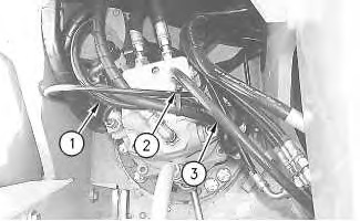
- Install 6V-8397 O-Ring Seal and 6V-9829 Cap on tee (2) at the swivel.
- Disconnect case drain hose (3) from tee (2) at the swing motor.
- Install 6V-8398 O-Ring Seal and 6V-9509 Face Seal Plug in the open end of case drain hose (3) .
- Install 6V-8398 O-Ring Seal and 6V-9830 Cap on the open end of tee (2) at the swing motor.
- Perform the following steps in order to engage the swing parking brake.
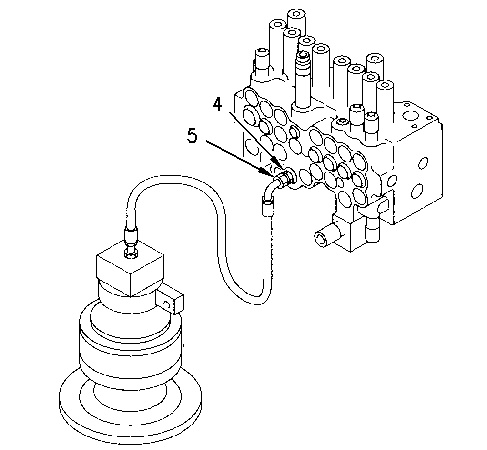
- Disconnect pilot line (5) from connector (4) at the main control valve.
Illustration 2 g00858712 (4) Connector
(5) Pilot line
- Install 4J-5477 O-Ring Seal and 6V-9828 Cap on connector (4) .
- Leave the end of pilot line (5) open to the atmosphere.
- Start the engine.
- Place the machine controls at the following settings: engine speed dial “10” and Low idle switch OFF. Refer to Testing and Adjusting, “Engine Performance – Test” for engine rpm settings.
- Place the hydraulic activation control lever in the UNLOCKED position.
- Increase the hydraulic oil temperature to 55° ± 5°C (131° ± 9°F).
- Slowly move the swing joystick and make sure that the swing parking brake is activated.
- Move the swing joystick fully for one minute. Measure the case drain oil.
- Stop the engine.
- Release the pressure in the hydraulic system. Refer to Testing and Adjusting, “Hydraulic System Pressure – Release”.
- Remove the cap from elbow (4) at the main control valve. Connect pilot line (5) to elbow (4) in order to disengage the swing parking brake.
- Repeat this test procedure three times in order to obtain three measurements. For each test procedure, swing the upper structure to a different position.
The following values specify the maximum acceptable flow of case drain oil when the swing relief pressure is set at 24000 ± 980 kPa (3500 ± 140 psi).
- New swing motor … 10 L/min (2.6 US gpm)
- Rebuilt swing motor … 20 L/min (5.3 US gpm)