|
|
|
|
|
|
| Illustration 1 | g00842072 |
|
Block Diagram of the Electrical System (1) Disconnect switch (2) Battery (3) Alternator circuit breaker (4) Power circuit (5) Heater relay (6) Glow plugs (7) Start/stop circuit (8) Engine shutdown timer (9) Engine shutdown solenoid (10) Starter motor (11) Key start switch (12) Neutral start switch (13) Neutral start relay (14) Starter relay (15) Starter control relay (16) Alternator (17) Charging circuit (18) Fuse box (19) Low current circuit (20) Air conditioner (21) Horn (22) Cab dome light (23) Travel alarm (24) Governor motor (25) Windshield wiper (26) Windshield washer (27) Light (28) Travel speed solenoid (29) Switch panel (30) Radio (31) Monitor |
|
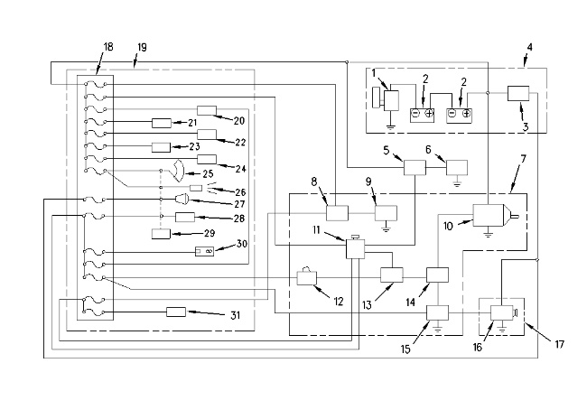
The electric system consists of power circuit (4), start/stop circuit (7), charging circuit (17) and low current circuit (19).
The power circuit supplies power to the electrical components. These components include battery (2), disconnect switch (1) and alternator circuit breaker (3) .
The start/stop circuit is used to start the engine. The start/stop circuit is used to stop the engine. The following components are used for the start/stop circuit: starter motor (10), starter relay (14), key start switch (11), engine shutdown solenoid (9), engine shutdown timer (8), starter control relay (15), neutral start relay (13) and neutral start switch (12). The preheat circuit is provided for cold weather starting aid. The preheat circuit is made up of key start switch (11), glow plugs (6), and heater relay (5) .
The charging circuit uses alternator (16) to charge battery (2) during engine operation. The charging circuit also supplies current to the low current circuit through fuse box (18) .
The low current circuit contains circuits for the following items:
- Chassis, cab and boom lights
- Windshield wiper and washer
- Radio
- Air conditioner
- Cab dome light
- Travel alarm
- Governor motor
- Monitor
- Horn
A description of circuit operation is given for the power circuit, the start/stop circuit, and the charging circuit. For additional information on the symbols that are used in the electrical circuit diagram, see the Electrical System Schematic.
|
|
|
|
|
|
| Illustration 2 | g00842844 |
|
Positions of the Key Start Switch (Right Console) (11) Key start switch (38) OFF position (39) Preheat position (40) ON position (41) Start position |
|
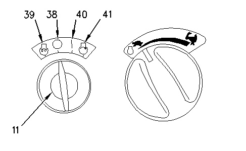
The key start switch is used to start the engine. The key start switch is used to stop the engine. The switch has four positions. Refer to Illustration 2 in the circuit descriptions that follow.
Note: The mechanical components in the circuit descriptions are not shown in the electrical schematics.
Power Circuit
|
|
|
|
|
|
| Illustration 3 | g00842841 |
|
Schematic of the Power Circuit (3) Alternator circuit breaker (11) Key start switch (16) Alternator (32) Fuses (33) Fuses (34) Fuses (35) Key on relay (36) Cab dome light relay (37) Chassis/Boom light relay |
|
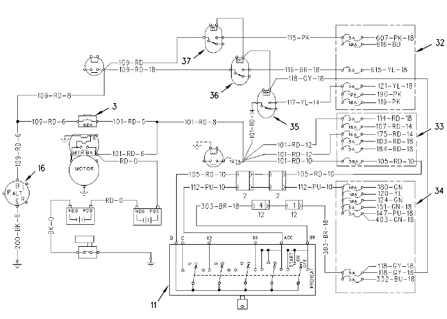
Current is available at the following components at all times: alternator circuit breaker (3), key start switch (11), alternator (16), fuses (33), key on relay (35), cab dome light relay (36) and chassis/boom light relay (37). When key start switch (11) is placed in the ON position (40), current is available at the following additional components: fuses (34) and fuses (32) .
Start/Stop Circuit
|
|
|
|
|
|
| Illustration 4 | g00842851 |
|
Schematic of the Start/Stop Circuit (8) Engine shutdown timer (9) Engine shutdown solenoid (10) Starter motor (11) Key start switch (12) Neutral start switch (13) Neutral start relay (14) Starter relay (42) Starter solenoid |
|
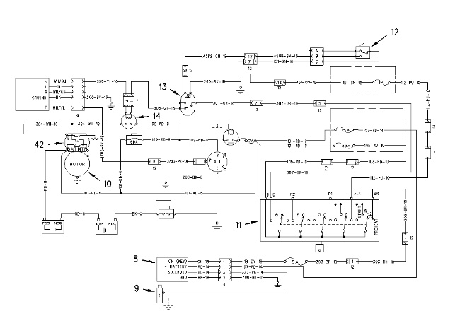
When key start switch (11) is placed in the ON position (40), and when the hydraulic lock switch is in the ON position, current flows through neutral start switch (12). The coil of neutral start relay (13) is energized, and the contacts in the neutral start relay are open. Starter relay (14) does not activate.
When key start switch (11) is placed in the START position (41), and when the hydraulic lock switch is in the OFF position, the contacts of neutral start relay (13) are closed. Current flows through the contacts of neutral start relay (13). Starter relay (14) activates. Current from the starter relay flows to starter motor (10). The plunger in starter solenoid (42) shifts. The starter motor pinion moves. The pinion engages the ring gear on the engine flywheel. The engine starts.
Releasing the key start switch returns the plunger in solenoid (42) to the original position. The starter motor pinion disengages from the flywheel ring gear.
When the key start switch is returned to the OFF position (38), the wire terminal 118-GY of engine shutdown timer (8) is open and the wire terminal 327-PK is closed. Current flows from engine shutdown timer (8) to engine shutdown solenoid (9). Engine shutdown solenoid (9) energizes. The engine fuel rack moves. The fuel stops flowing to the engine. The engine stops.
The wire terminal 327-PK of engine shutdown timer (8) is automatically opened after approximately 6 seconds. No current flows to engine shutdown solenoid (9). Engine shutdown solenoid (9) deactivates.
Preheat Circuit
|
|
|
|
|
|
| Illustration 5 | g00842854 |
|
Schematic of the Preheat Circuit (5) Heater relay (6) Glow plugs (11) Key start switch |
|
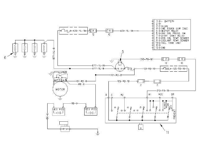
The preheat circuit is an engine starting aid in cold weather. Cold weather conditions exist when the temperature is below 0 °C (32.0 °F).
When key start switch (11) is placed in the PREHEAT position (39), the contacts of heater relay (5) are closed. Current flows through heater relay (5) to glow plugs (6). Glow plugs (6) are located in the engine. Glow plugs (6) increase the temperature in the engine cylinder. The increased temperature aids in starting the engine.
Charging Circuit
|
|
|
|
|
|
| Illustration 6 | g00842867 |
|
Schematic of the Charging Circuit (2) Battery (3) Alternator circuit breaker (11) Key start switch (16) Alternator |
|
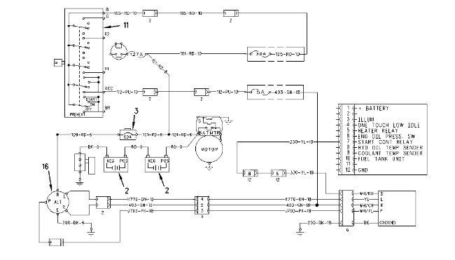
When key start switch (11) is placed in the ON position (40), current is available to alternator (16). When the engine is started, the alternator generates voltage from the available current. In self-excited alternators, the available current is not required because the voltage is generated internally.
When the engine is in normal operation, the charging current from the “B” terminal of the alternator goes through alternator circuit breaker (3) to battery (2). Alternator (16) also supplies current to the electrical components in the electrical system.