Engine Output Control
|
|
|
|
|
|
| Illustration 1 | g00845469 |
|
Positions of Engine Speed Dial (Right Console) (1) Engine speed dial (15) TORTOISE position (16) RABBIT position |
|

|
|
|
|
|
|
| Illustration 2 | g00845475 |
|
Rear of Engine (2) Governor lever |
|
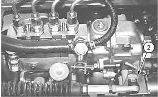
Engine speed dial (1) is located on the right console. The dial controls an actuator that moves governor lever (2). The position of governor lever (2) determines the engine speed. When the engine speed dial is in the TORTOISE position (15), the engine runs at the lowest speed (low idle). When the engine speed dial is in the RABBIT position (16), the engine runs at the highest speed (high idle). When the dial is between the two positions, governor lever (2) moves to a position between low idle and high idle.
Switch for One Touch Low Idle
|
|
|
|
|
|
| Illustration 3 | g00845478 |
|
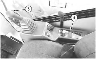
Right Console (3) Switch for one touch low idle (4) Monitor panel |
|
|
|
|
|
|
|
| Illustration 4 | g00845485 |
|
Right Console (4) Monitor panel (5) Low idle indicator |
|
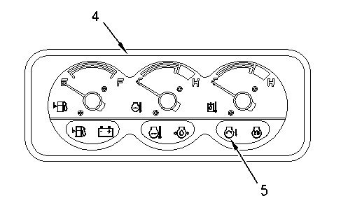
The switch for one touch low idle (3) is located on the top of the right control lever. Pressing the switch for one touch low idle (3) activates the low idle system. All hydraulic controls must be in the neutral position in order to activate the low idle system. The engine speed decreases to low idle speed regardless of the position of engine speed dial (1). Low idle indicator (5) on monitor panel (4) turns ON when the low idle system is activated.
Pressing the switch for one touch low idle (3) again deactivates the low idle system. The engine speed is restored to the speed that is set by engine speed dial (1). Low idle indicator (5) on monitor panel (4) turns OFF when the low idle system is deactivated.
Operation
|
|
|
|
|
|
| Illustration 5 | g00845486 |
|
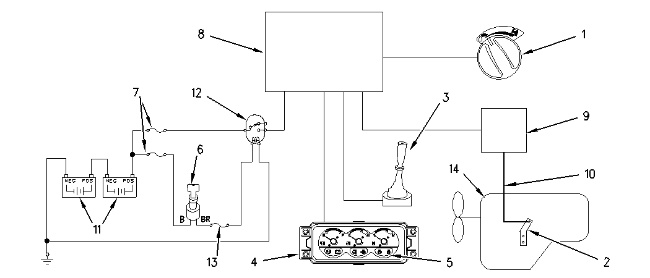
Schematic of the Engine Control System (1) Engine speed dial (2) Governor lever (3) Switch for one touch low idle (4) Monitor panel (5) Low idle indicator (6) Key start switch (7) Fuses (8) Controller (9) Governor actuator (10) Accelerator cable (11) Battery (12) Relay (13) Fuse (14) Engine |
|
|
|
|
|
|
|
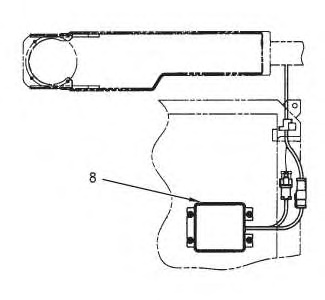
| Illustration 6 | g00845489 |
|
Components under the operator seat (8) Controller |
|
|
|
|
|
|
|
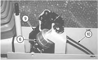
| Illustration 7 | g00845494 |
|
Components in the right console (6) Key start switch (9) Governor actuator (10) Accelerator cable |
|
The positive terminal of battery (11) is always connected to fuses (7). When the engine is started, battery current flows from terminal B to terminal BR on key start switch (6). The current flows through fuse (13), and the current energizes the coil on relay (12). The relay closes, and current flows from the battery to controller (8). The controller sends a signal to governor actuator (9). The governor actuator adjusts the tension of accelerator cable (10). The tension of the accelerator cable depends on the position of engine speed dial (1) .
The end of accelerator cable (10) is connected to governor lever (2) on engine (14). As the accelerator cable moves, governor lever (2) moves within the high idle position and the low idle position. These positions are selected by engine speed dial (1). The engine runs between the high idle speed and the low idle speed.
When the switch for one touch low idle (3) is pressed, controller (8) sends a signal to governor actuator (9). The governor actuator adjusts the tension of accelerator cable (10), and the engine speed decreases to the low idle speed. (The accelerator cable moves to the full stroke position.) This action occurs regardless of the position of the engine speed dial. At the same time, controller (8) supplies current to the monitor panel, and the low idle indicator comes ON.
Controller (8) sends a signal to governor actuator (9) when the switch for one touch low idle (3) is pressed again. Governor actuator (9) adjusts the tension of accelerator cable (10). The engine speed increases to the speed that was selected by engine speed dial (1). At the same time, the controller causes low idle indicator (5) to go OFF.
The signals from controller (8) stop automatically when a continuous power supply level has been maintained for more than 8 ± 3 seconds. When engine speed dial (1) is operated again, the activation signals are restored.
When the engine speed is controlled by the engine speed dial, the engine runs at the following speeds: (The engine is unloaded and the low idle indicator is OFF.)
- Engine speed is 2320 ± 25 rpm when the engine speed dial is in the RABBIT position.
- Engine speed is 950 ± 50 rpm when the engine speed dial is in the TORTOISE position.
- Engine speed is 950 ± 50 rpm to 2320 ± 25 rpm when the engine speed dial is in a position between the TORTOISE and the RABBIT position.
Engine speed is 950 ± 80 rpm when the low idle system is activated. (The low idle indicator is ON.)