|
|
|
|
|
|
| Illustration 1 | g02174463 |
|
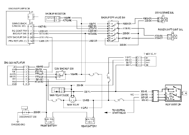
This diagram is for the backup switch. The switch is found on the 312C, 315C, 318C, 319C, 320C, and 322C . |
|
|
|
|
|
|
|
| Illustration 2 | g02176551 |
|
This diagram is for the backup switch. The switch is found in the 321C. |
|

|
|
|
|
|
|
| Illustration 3 | g02176552 |
|
This diagram is for the 325C and 330C backup switch. |
|

The backup system is used when the controller is not able to control the machine properly. The backup system is provided so that the machine can be moved or an operation can be performed. The monitor will indicate when the backup system is active.
Engine Speed Control
The engine speed can be controlled. Control is enabled by the engine speed control switch. When the switch is placed in the rabbit position, the engine speed will be increased. When the switch is placed in the tortoise position, the engine speed will be decreased.
Pump Control
During a backup condition, the output of the pump will be reduced 60% to 80% of the rated output. The power shift pressure is fixed. Care should be taken in order to prevent the engine from stalling. This condition could occur during machine operation while the engine speed dial is in a low position or the output of the engine has been decreased significantly.
Swing Parking Brake
The swing parking brake can be released during a backup condition. However, the brake is under activation when the hydraulic oil supply is stopped. The hydraulic oil supply is stopped when the engine is stopped or the hydraulic lock lever is moved to the lock position.