Power Shift Solenoid
The proportional reducing solenoid valve changes the electrical signal from the controller into a hydraulic signal for the hydraulic pump. The hydraulic signal (power shift pressure) is used to regulate the output of the hydraulic pump. The controller varies the current (PWM signal) to the solenoid and the solenoid valve modulates the power shift pressure. The controller varies the current to the solenoid according to the engine speed.
Solenoid Valve
|
|
|
|
|
|
| Illustration 1 | g00666610 |
|
Schematic Symbol |
|

The solenoid valve is designed to direct the flow of hydraulic oil through the hydraulic system. The controller will activate the proper solenoid valves according to the input from switches on the monitor panel and the pressure switches in the hydraulic system of the machine. When the solenoids are activated, a solenoid receives ground from the controller. The travel speed solenoid is activated when “HIGH” is selected in the travel speed mode. The “rabbit” travel speed indicator is illuminated when this mode is active.
The solenoids have a connector with two contacts. One contact receives a ground signal from the corresponding connector of the controller. The other solenoid contacts are connected to a +battery source in the fuse panel.
Power Shift Solenoid
|
|
|
|
|
|
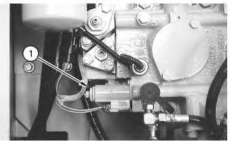
| Illustration 2 | g00778231 |
|
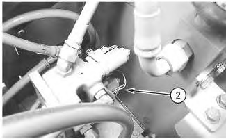
Power Shift Solenoid (1) For The 312C and 315C |
|
|
|
|
|
|
|
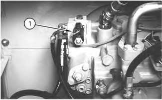
| Illustration 3 | g00685868 |
|
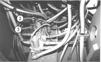
Power Shift Solenoid (1) For The 318C, 319C, 320C, 322C, and 325C Photo for 318C, 319C, 320C, 322C, 325C, and 330C |
|
|
|
|
|
|
|
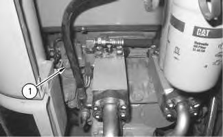
| Illustration 4 | g00986691 |
|
Power Shift Solenoid (1) for 321C |
|
The controller adjusts the current that drives the solenoid according to the following conditions:
- The position of the engine speed dial
- The actual engine speed
- The delivery pressure of the pump
- The pressure of the power shift system
Travel Speed Solenoid and Swing Parking Brake Solenoid
|
|
|
|
|
|
| Illustration 5 | g00778233 |
|
Straight Travel Solenoid (2) and Swing Parking Brake Solenoid Valve (3) for 312C |
|
|
|
|
|
|
|
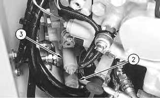
| Illustration 6 | g00685886 |
|
Straight Travel Solenoid (2) and Swing Parking Brake Solenoid (3) for 319C, 320C, 322C, 325C, and 330C |
|
The travel speed solenoid changes the speed of the travel motor from high speed to low speed and vice versa. When the low speed mode has been selected, the solenoid is not energized. The displacement of the travel motor is controlled by the travel speed solenoid. If the travel motor is in the high speed mode and the controller detects a pressure that is too high, the travel speed solenoid will be de-energized and the travel motor will now be in the low speed mode.
The swing parking brake solenoid valve is energized in order to release the swing brake, when the implement, the swing or the tool is operated. The swing parking brake solenoid valve will be de-energized and the swing brake will be applied 6.5 seconds after a control lever has been returned to neutral.
Straight Travel Solenoid
|
|
|
|
|
|
| Illustration 7 | g00778232 |
|
Straight Travel Solenoid (2) for 315C |
|
|
|
|
|
|
|
| Illustration 8 | g00685928 |
|
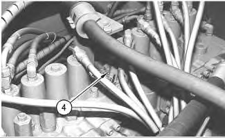
Straight Travel Solenoid (4) for 318C, 319C, 320C, 322C, 325C, and 330C |
|
|
|
|
|
|
|
| Illustration 9 | g00986708 |
|
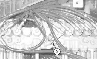
Straight Travel Solenoid (5) for 321C |
|
The straight travel solenoid will be energized when the right travel pedal and the left travel pedal are depressed at the same time with an implement or swing function active. Depression of the travel pedals will close the travel right pressure switch and the travel left pressure switch. The active implement or swing function will close the implement/swing pressure switch. When the required conditions are satisfied, the ECM wiil energize the straight travel solenoid. Then, the straight travel valve will divert hydraulic pressure from the right hydraulic pump to both travel motors. The left hydraulic pump will supply the pressure to operate the implements and swing functions. This mode of pump operation will prevent any pressure differential between the right travel motor and the left travel motor which will enable the machine to travel straight.