|
|
|
|
|
|
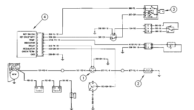
| Illustration 1 | g00776425 |
|
Schematic of the Starting Aid Circuit for the 312C, 315C, and 318C (1) Heater relay (2) Air heater (3) Starter switch (4) Heater control unit |
|
|
|
|
|
|
|
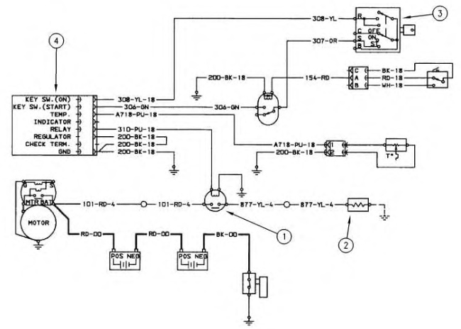
| Illustration 2 | g00695833 |
|
Schematic of the Starting Aid Circuit for The 319C, 320C and 321C (1) Heater relay (2) Air heater (3) Starter switch (4) Heater control unit |
|
|
|
|
|
|
|
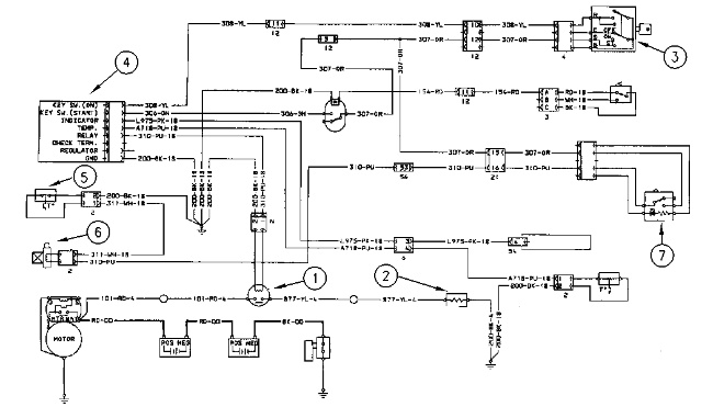
| Illustration 3 | g00776426 |
|
Schematic of the Starting Aid Circuit for The 322C Series (1) Heater relay (2) Air heater (3) Starter switch (4) Heater control unit (5) Engine coolant temperature switch (6) Start aid solenoid (7) Start aid switch |
|
|
|
|
|
|
|
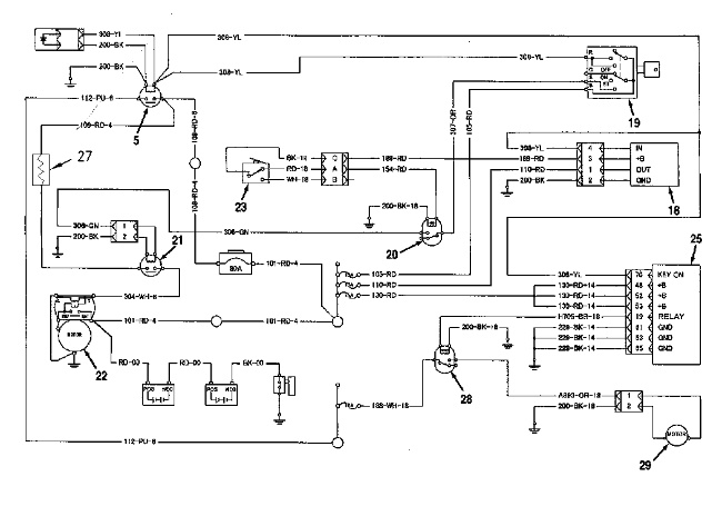
| Illustration 4 | g00824767 |
|
Schematic of the Starting Aid Circuit for The 325C and 330C (19) Starter Switch (25) Engine Controller (21) Heater Relay (27) Air Heater |
|
The circuit for the starting aid is an auxiliary circuit. This circuit is used to aid the engine in starting during cold weather below 10 °C (50 °F).
After the starter switch is moved to the ON position, the time for preheating is determined by the heater control unit. The time for preheating is determined according to the temperature of the coolant in the engine. Power is sent to the air heater relay for the amount of time that is determined by the heater control unit. The contacts of the air heater relay close and power is sent to the air heater. The monitor will indicate “Air Heater Operating”. This indication will disappear when heating is no longer operating. The air heater will also operate with the starter switch in the “START” position.