Two preliminary temporary adjustment procedures must be performed:
- A temporary setting of the main relief valve pressure is required.
- A temporary line relief setting of the head end of the boom cylinder is required.
Four relief valves are involved in this procedure:
- main relief valve
- head end of the boom line relief valve
- boom lowering control valve of the right cylinder
- boom lowering control valve of the left cylinder
Note: A New specification is the performance that can be expected for a new machine. A Rebuild specification is the performance that can be expected after rebuilding the components of a system. Performance beyond Service Limit specifications is an indication of these problems: improper adjustment, wear, damage of relief valves and damage of pumps.
| Relief Valve | Specifications | Torque for Locknut | ||
|---|---|---|---|---|
| New | Rebuild | Service Limit | ||
| (A) Main relief valve | 34300 ± 490 kPa (4950 ± 72 psi) | 34300 ± 490 kPa (4950 ± 72 psi) | 32340 to 34790 kPa (4700 to 5050 psi) | 50 ± 10 N·m (37 ± 7 lb ft) |
| (B) Boom cylinder line (head end) | 36800 ± 1470 kPa (5350 ± 215 psi) | 36800 ± 1470 kPa (5350 ± 215 psi) | 33850 to 38270 kPa (4920 to 5565 psi) | 20 ± 2 N·m (14 ± 4 lb ft) |
| (C) Boom lowering control valve | ||||
| Required Tools | ||
| Part Number | Description | Qty |
| 9U-7400 | Multitach Tool Group | 1 |
| 8T-0470 | Thermometer group | 1 |
| Relief Valves | Pressure change With One Turn Of Adjustment Screw |
|---|---|
| Main valves | 14400 kPa (2100 psi) |
| Line relief valve | 11000 kPa (1600 psi) |
Note: Pressure values in Table 3 are approximate values. Use a pressure gauge for adjustment.
Note: Normal operations of the engine and pumps are necessary for the pressure adjustments. If the results of the pressure adjustment are not correct, then the engine and the pump characteristic curve needs to be checked. Slow output flow from the pump is an indication of air in the hydraulic system. Make sure that no air is present in the hydraulic system. Refer to Testing And Adjusting, “Air (Main Hydraulic Pump) – Purge”.
Note: Always make final pressure adjustments on pressure rise.
|
|
|
|
|
|
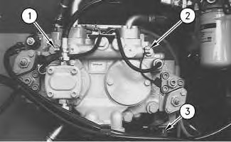
| Illustration 1 | g00666193 |
|
Pump compartment (1) Pressure tap for delivery pressure from the right pump (drive pump) (2) Pressure tap for delivery pressure from the left pump (idler pump) (3) Pressure tap (power shift pressure) |
|
- Position the machine on level ground.
- Stop the engine.
- Release the pressure in the hydraulic system. Refer to Testing And Adjusting, “Hydraulic System Pressure – Release”.
- Connect a 60000 kPa (8700 psi) pressure gauge to pressure tap (1). Connect a 60000 kPa (8700 psi) pressure gauge to pressure tap (2) .
- Connect a 6000 kPa (870 psi) pressure gauge to pressure tap (3). This is used to monitor power shift pressure.
- Start the engine.
- Place the machine controls at the following settings: engine speed dial “10” and AEC switch OFF. Refer to Testing And Adjusting, “Engine Performance Test” for engine rpm settings.
- Increase the hydraulic oil temperature to 55° ± 5°C (131° ± 9°F).
- Slowly move the joystick for the bucket to the BUCKET OPEN position (bucket cylinder rod at the fully retracted position).
- Check the main relief valve pressure setting at pressure tap (1) .
- Return the joystick for the bucket to the NEUTRAL position.
- The main relief valve pressure setting should be 34300 ± 490 kPa (4950 ± 72 psi). If the main relief valve is not within the specification, adjust the main relief valve pressure setting to the correct pressure specification before performing Step 13. Refer to Testing and Adjusting, “Main Relief Valve – Test and Adjust”.
- A temporary setting of the main relief valve is required before any line relief valve can be adjusted. To make the temporary setting, loosen locknut (5) and turn adjustment screw (4) clockwise for one half turn. Tighten locknut (5). Use the torque specification in Table 1.
|
|
|
|
|
|
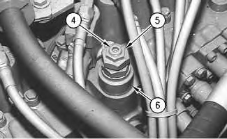
| Illustration 2 | g00666196 |
|
Top of main control valve (4) Adjustment screw (5) Locknut (6) Main relief valve |
|
- Refer to Systems Operation/Testing and Adjusting, RENR 3814, “320C Excavator Engine and Pump Control”, “Using Service Mode”. Start service mode. Adjust the power shift pressure. Input a fixed power shift pressure of 2900 kPa (420 psi).
- The permanent pressure setting for the head end of the boom cylinder is 36800 ± 1470 kPa (5350 ± 215 psi).
- To adjust the line relief valve pressure setting of the boom cylinder head end, move the joystick for the boom until the boom is at the full BOOM RAISE position (full extension of boom cylinders). Hold the joystick for the boom in this position.
- Check the pressure in the boom cylinder head end on the pressure gauge at pressure tap (1) .
- Return the joystick for the boom to the NEUTRAL position.
- The pressure setting of the boom line relief valve is read at pressure tap (1). The pressure setting of the boom line relief valve should be 36800 ± 1470 kPa (5350 ± 215 psi). If the boom lowering control valves are set at a lower pressure, the boom lowering control valves will relieve pressure first. A lower pressure will be read. Continue to step 20.
- A temporary setting of the head end of the boom line relief valve is required before the boom lowering control valve can be adjusted. To make the temporary setting, loosen locknut (14) on the line relief valve for the head end of the boom cylinder. Turn adjustment screw (15) for one half turn. Tighten the locknut. This should ensure that the line relief valve is high enough.
- The following test and adjustment procedures properly set the boom lowering control valves on each of the boom cylinders. The temporary settings of the main relief valve and the line relief valve must be performed before the boom lowering control valves are set.
- During the following procedure, carefully note the number of turns for adjustment screw (19). Also, take note of the direction of the turns.
- Loosen locknut (20) on the boom lowering control valve for the left cylinder. Turn adjustment screw (19) clockwise until the adjustment screw contacts the bottom. Do not overtighten adjustment screw (19) . Be sure to remember the number of turns. Tighten locknut (20) .
|
|
|
|
|
|
| Illustration 3 | g00730392 |
|
(19) Adjustment screw (20) Locknut (21) Relief valve (22) Boom lowering control valve (23) Manual valve for boom lowering |
|

- Move the joystick for the boom to the full BOOM RAISE position. Hold the joystick for the boom in this position and check the pressure gauge reading at pressure tap (1) .
- Return the joystick for the boom to the NEUTRAL position.
- The pressure gauge reading should be 36800 ± 1500 kPa (5350 ± 215 psi). If the pressure gauge reading at pressure tap (1) is not within the specification, adjust the relief valve on the right cylinder. In order to adjust the relief valve, loosen locknut (20) on the right boom lowering control valve. Turn adjustment screw (19). Tighten the locknut.
- Recall the number of clockwise turns on the left boom lowering control valve. Loosen locknut (20) on the left boom lowering control valve. Reverse adjustment screw (19). Make the recalled number of turns. Make one additional quarter turn in order to decrease the pressure setting below 36800 ± 1500 kPa (5350 ± 215 psi). Tighten the locknut.
- Fully extend the boom cylinders. Hold the implement control lever in the Boom Raise position. Read the pressure at pressure tap (1) .
- Return the joystick for the boom to the NEUTRAL position.
- The pressure gauge reading should be 36800 ± 1500 kPa (5350 ± 215 psi). If the pressure gauge reading at pressure tap (1) is not within the specification, adjust the relief valve. In order to adjust the relief valve, loosen locknut (20) on the left boom lowering control valve. Turn adjustment screw (19). Tighten the locknut.
- Reset the line relief valve for the head end of the boom cylinder. Refer to Testing and Adjusting, RENR3817, “Relief Valve (Line) – Test and Adjust”.
- Refer to Systems Operation/Testing and Adjusting, RENR3814, “320C Excavator Engine and Pump Control”, “Using Service Mode”. Exit service mode.
- Reset the main relief valve pressure after resetting the line relief valve. Refer to Testing and Adjusting, RENR3817, “Relief Valve (Main) – Test and Adjust”.