Conditions Which Generate This Code:
|
|
|
|
|
|
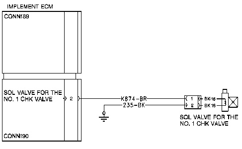
| Illustration 1 | g00796993 |
|
Schematic of the Solenoid Valve for the Number One Check Valve |
|
This diagnostic code is associated with the solenoid valve for the number one check valve. This diagnostic code is recorded when the implement ECM reads the current of the solenoid as being below normal.
The possible causes are listed:
- The signal circuit of the solenoid is open.
- The return circuit of the solenoid is open.
- The solenoid has failed.
- The implement ECM has failed. This is unlikely.
Note: Ensure that the diagnostic code for the solenoid is active.
Note: The following procedure can create numerous related diagnostic codes. When all harnesses are reconnected, the related diagnostic codes will be shown as being not active. Clear all related diagnostic codes after this procedure is completed.
Test Step 1. CHECK THE SOLENOID.
- Turn the disconnect switch and the key start switch to the ON position. DO NOT start the engine.
- Disconnect the solenoid with the diagnostic code from the machine harness.
- At the machine harness connector for the solenoid, place a jumper wire from contact 1 (wire K874-BR) to contact 2 (wire 235-BK).
- Determine if CID 1522 FMI 05 is present. Check the “ACTIVE ERROR” screen on the monitor.
Expected Result:
The diagnostic code is not active when the jumper wire is installed.
Results:
- YES – The diagnostic code is not active when the jumper wire is installed. The circuit is correct.
Repair: The solenoid has failed. Repeat this test step “CHECK THE SOLENOID” in order to verify the solenoid failure. Replace the solenoid. Verify that the new solenoid corrects the problem.
STOP
- NO – The diagnostic code remains active. Proceed to test step 2.
Test Step 2. CHECK THE SOLENOID CIRCUIT FOR AN OPEN.
- Turn the key start switch and the disconnect switch to the OFF position.
- Disconnect the CONN189 and CONN190 machine harness connectors from the implement ECM.
- At the machine harness connector for the solenoid, the jumper wire remains installed.
- At the CONN190 machine harness connector of the implement ECM, measure the resistance from contact CONN190-2 (wire K874-BR) to frame ground.
Expected Result:
The resistance should be less than 5 ohms.
Results:
- OK – The resistance is less than 5 ohms. The machine harness is correct. Proceed to test step 3.
- NOT OK – The resistance is greater than 5.0 ohms. The resistance measurement is not correct. There is an open circuit in the machine harness.
Repair: The open is in the wire for the solenoid signal of the machine harness. Repair the machine harness or replace the machine harness.
STOP
Test Step 3. CHECK THE RESISTANCE OF THE SOLENOID.
- The key start switch is in the OFF position.
- Remove the jumper wire from the previous test step.
- At the connector for the solenoid, measure the resistance of the solenoid from contact CONN190-1 (wire K874-BR) to contactCONN190-2 (wire 235-BK).
Expected Result:
The resistance measurement should be between 5 ohms and 19 ohms.
Results:
- OK – The resistance measurement is correct. Proceed to test step 4.
- NOT OK – The resistance measurement is NOT correct. The solenoid has failed.
Repair: Replace the solenoid. Calibrate the solenoid. See Testing and Adjusting, “Relief Valve (Line) – Test and Adjust (Number 1 Relief Valve and Number 2 Relief Valve)” for the Tool Control System.
STOP
Test Step 4. CHECK IF THE DIAGNOSTIC CODE REMAINS.
- Inspect the harness connectors and clean the contacts of the harness connectors.
- Reconnect all harness connectors. Ensure that the connectors are properly seated and ensure that the connections are tight.
- Turn the disconnect switch and the key start switch to the ON position.
- Clear all inactive diagnostic codes.
- Operate the machine.
- Stop the machine.
- Determine if the CID 1522 FMI 05 is present. Check the “ACTIVE ERROR” screen on the monitor.
Expected Result:
The diagnostic code for the solenoid is NOT present.
Results:
- YES – The diagnostic code is NO longer active. The diagnostic code does not exist at this time. The initial diagnostic code was probably caused by a poor electrical connection or a short at one of the harness connectors that was disconnected and reconnected. Resume normal machine operation.STOP
- NO – The diagnostic code has not been corrected.
Repair: It is unlikely that the implement ECM has failed. Exit this procedure and perform this procedure again. If the cause of the diagnostic code is not found, replace the implement ECM. See Testing and Adjusting, “Electronic Control Module (ECM) – Replace” for the Tool Control System.
STOP