This calibration is used to memorize the power shift pressure for the proportional reducing valve. Be sure to perform this calibration when the proportional reducing valve or the controller has been replaced.
- Install a pressure gauge of 4900 kPa (710 psi) to the tap for the power shift pressure.
- Set the backup switch to the AUTO position.
- Raise the hydraulic oil temperature to 50 °C (122 °F).
- Enter the service mode.
|
|
|
|
| Illustration 1 |
g00688851 |
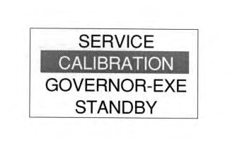
- Highlight the second line by using the arrow keys. Scroll through the display on the second line until the display shows “CALIBRATION” by using the arrow keys.
|
|
|
|
| Illustration 2 |
g00689451 |
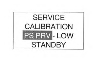
- Highlight the third line by using the arrow keys. The name of the device for the calibration is displayed on the third line. Scroll through the display until the display shows “PS PRV” by using the arrow keys. The power shift pressure is calibrated for the low pressure and the high pressure.
- Low pressure 500 kPa (72 psi)
- High pressure 2500 kPa (362 psi)
|
|
|
|
| Illustration 3 |
g00689455 |
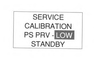
- The area that is highlighted is moved to the right side by using the “menu” key in order to change between low pressure and high pressure. Then, the arrow keys are used in order to change the display from low pressure to high pressure.
|
|
|
|
| Illustration 4 |
g00689465 |
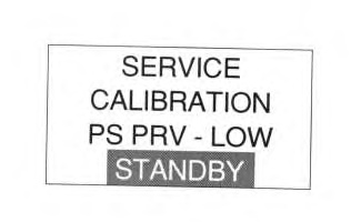
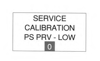
- Highlight the fourth line by using the arrow keys. Then, change the value. Press the “OK” key.
|
|
|
|
| Illustration 5 |
g00689483 |
- The fourth line will show a numerical value. The engine speed should be increased to a position of 10 on the engine speed dial. The pressure gauge will indicate the actual power shift pressure. Note the actual value that is shown on the pressure gauge. Use the left arrow key and the right arrow key to enter the value that is shown on the pressure gauge into the fourth line of the display on the monitor. The value should be set as close to the actual pressure as possible. The power shift pressure will change by approximately 30 kPa (4.3 psi) per step. The monitor can correct the pressure by ±30 kPa (4.3 psi).
- The “setting” key is pressed in order to save the value of the power shift pressure. After the value has been saved, the third line will be highlighted.
|
|
|
|
| Illustration 6 |
g00689488 |
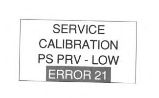
- Refer to the following table 1 if an error is present on the display. The error will be displayed on the fourth line of the message center.
- Repeat the same procedure for the high pressure.
Table 1
| List Of Error Codes |
| Display |
Description Of The Error |
Corrective Action |
| ERROR 01 |
Being calibrated by another device |
Stop the calibration of the other component. Perform calibration again. |
| ERROR 02 |
Being calibrated by another module |
Stop the calibration of the other component. Perform calibration again. |
| ERROR 03 |
Failure of the interlock signal |
Troubleshoot the confirmation of the signals for communication. |
| ERROR 21 |
Abnormal component operation |
Confirm the active error code. Troubleshoot the problem according to the component. |


