|
|
|
|
|
|
| Illustration 1 | g00890458 |
|
(1) Pilot line (2) Line (3) Line (4) Bucket cylinder (5) Main control valve (6) Return line (7) Center bypass passage (8) Center bypass passage (9) Bucket control valve (10) Spring (11) Orifice (12) Load check valve (13) Spring (14) Negative flow control orifice (15) Pilot control valve (boom and bucket) (16) Parallel feeder passage (17) Return passage (18) Pilot line (19) Negative flow control line (20) Pilot oil manifold (21) Left pump (22) Right pump (23) Pilot pump |
|
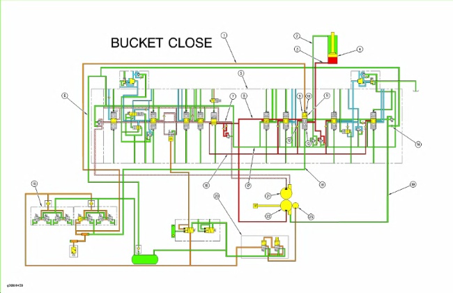
The oil delivery for the bucket hydraulic circuit is supplied by right pump (22) only.
|
|
|
|
|
|
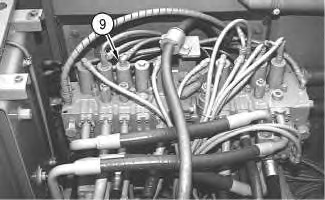
| Illustration 2 | g00697166 |
|
(9) Bucket control valve |
|
The oil delivery from right pump (22) flows through center bypass passage (8) in main control valve (5) to bucket control valve (9) . The oil delivery from left pump (21) flows through center bypass passage (7) in main control valve (5) . Illustration 1 shows the main control valve when only the bucket hydraulic circuit is activated.
When the hydraulic activation control lever is in the UNLOCKED position, the oil delivery from pilot pump (23) flows through pilot oil manifold (20) to pilot control valve (15) . When the joystick for the bucket is moved to the BUCKET CLOSE position, pilot oil flows through pilot control valve (15) and pilot line (1) to bucket control valve (9) . The pilot oil pressure shifts the spool in the bucket control valve against spring (13) . The pilot oil on the other end of the spool in the bucket control valve flows through pilot line (18) and pilot control valve (15) to the hydraulic tank.
Since the spool in the bucket control valve is fully shifted, center bypass passage (8) is blocked. None of the oil delivery from the right pump flows to negative flow control orifice (14) and no negative flow control pressure is created in center bypass passage (8) . Since no negative flow control pressure is sent through negative flow control line (19) to the right pump regulator, the right pump regulator moves the swashplate of the right pump toward the maximum angle position. The output flow rate of the right pump is increased and flows through parallel feeder passage (16) , load check valve (12) , bucket control valve (9) and line (3) to the head end of bucket cylinder (4) .
Since the oil delivery for the bucket hydraulic circuit is supplied by the right pump only, the negative control pressure in center bypass passage (7) is high. Left pump (21) remains at the destroked position.
ReferenceFor more information concerning the negative flow control operation, refer to Systems Operation, “Negative Flow Control System”.
The return oil from the rod end of the bucket cylinder flows through line (2) , orifice (11) in bucket control valve (9) , return passage (17) and return line (6) to the hydraulic tank. Orifice (11) restricts the return oil from the rod end of the bucket cylinder.
The BUCKET OPEN operation is similar to the BUCKET CLOSE operation.
When the joystick for the bucket is moved to the BUCKET OPEN position, pilot oil flow from pilot control valve (15) flows through pilot line (18) to the bucket control valve. The spool in the bucket control valve shifts against the force of spring (10) . The oil delivery from the right pump now flows to the rod end of the bucket cylinder.
When the joystick for the bucket is in the NEUTRAL position, springs (10) and (13) maintain the spool in the bucket control valve in the NEUTRAL position. The oil flow from the head end and the rod end of the bucket cylinder is blocked.