|
|
|
|
|
|
| Illustration 1 | g00688385 |
|
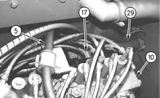
Main control valve compartment (return circuit) (5) Makeup line (makeup oil to swing motor) (10) Main control valve (17) Slow return check valve (29) Inlet line to oil cooler (18) |
|
|
|
|
|
|
|
| Illustration 2 | g00688460 |
|
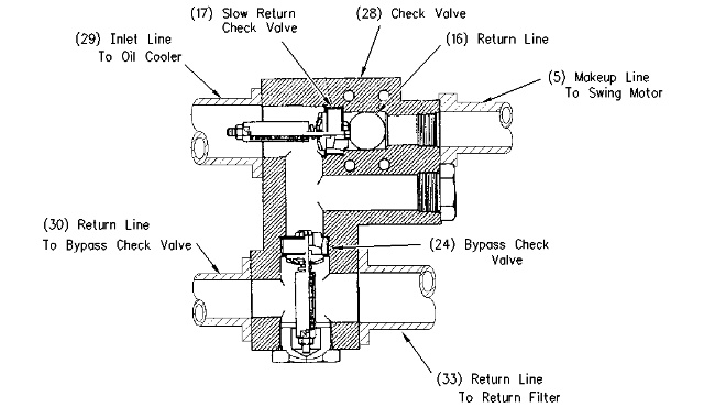
Slow return check valve and bypass check valve (5) Makeup line (makeup oil to swing motor) (16) Return line (17) Slow return check valve (24) Bypass check valve (28) Check valve (29) Inlet line to oil cooler (18) (30) Return line to bypass check valve (33) Return line (return flow to return filter) |
|
Slow return check valve (17) is contained in check valve (28). Slow return check valve (17) is located between the main control valves and the hydraulic tank in the return circuit. The slow return check valve restricts the return oil flow. This restriction causes a pressure increase in return line (16) and makeup line (5) .
If cavitation occurs in the swing motor, oil from return line (16) flows into makeup line (5). This makeup oil is supplied to the inlet port of the swing motor in order to prevent cavitation in the swing motor.
Note: For more information on the makeup operation, refer to System Operation, “Oil Makeup (Swing System)”.
The return oil flow through slow return check valve (17) is divided into two flow paths. A portion of the oil flows through inlet line (29) to the hydraulic oil cooler. The cooled oil from the hydraulic oil cooler flows through return line (30) and the return filter to the hydraulic tank. The remainder of the oil flow from slow return check valve (17 ) flows through bypass check valve (24) and the return filter to the hydraulic tank. Bypass check valve (24) is contained in check valve (28).

