The boom lowering control valves are located on the head end of the boom cylinders.
The boom lowering control valve has two functions:
- The boom lowering control valve prevents the boom from falling if a hydraulic supply line fails or if a supply tube to a boom cylinder fails.
- The boom lowering control valve allows the operator to manually lower the boom when the engine is shut down.
Reference: For information on lowering the boom manually, see Operation and Maintenance Manual, “Equipment Lowering with Engine Stopped”.
|
|
|
|
|
|
| Illustration 1 | g00833330 |
|
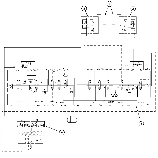
Partial schematic (1) Boom cylinders (2) Boom lowering control valves (3) Main control valve (4) Pilot control valve |
|
BOOM RAISE Operation
|
|
|
|
|
|
| Illustration 2 | g00833390 |
|
Boom lowering control valve (1) Port (boom cylinder head end) (2) Passage (3) Spring chamber (4) Check valve (5) Spring (6) Passage (7) Line relief valve (8) Port (9) Passage (10) Port (11) Spool (12) Passage |
|
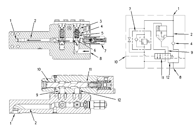
When the operator moves the joystick to the BOOM RAISE position, oil from the main control valve flows through port (8) in the boom lowering control valve. As the oil pressure increases, check valve (4) shifts against the force of spring (5). This allows oil to flow through passage (6) and passage (2) to the head end of the boom cylinders. The rod is extended and the boom raises.
BOOM LOWER Operation
|
|
|
|
|
|
| Illustration 3 | g00834081 |
|
Boom lowering control valve (1) Port (boom cylinder head end) (2) Passage (7) Line relief valve (8) Port (9) Passage (10) Port (11) Spool (12) Passage (13) Orifice (14) Notch (15) Port (16) Spring (17) Orifice (18) Valve (19) Spring chamber (20) Passage |
|
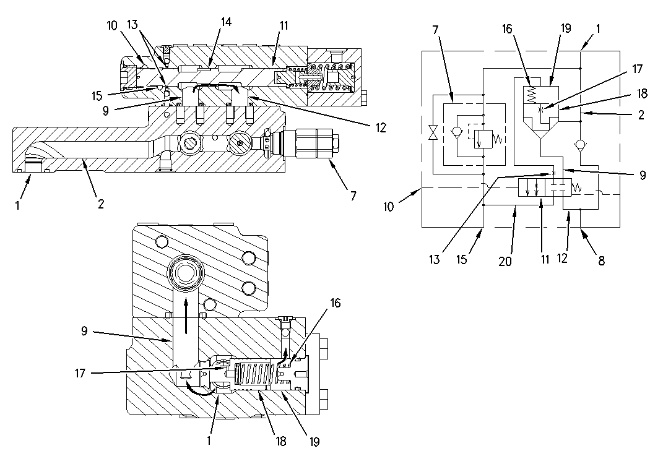
When the operator moves the joystick to the BOOM LOWER position, pilot oil flows from the pilot control valve to port (10) of the boom lowering control valve. The pilot pressure moves spool (11) to the right. Orifices (13) open. This allows oil from spring chamber (19) to flow through passage (20) to port (15) .
When orifices (13) are opened, the pressure in spring chamber (19) decreases. Valve (18) is shifted to the right against the force of spring (16) by the pressure in passage (2). This connects passages (2) and (9) .
As the joystick is moved further to the BOOM LOWER position, the pilot pressure in port (10) increases. Because spool (11) is shifted to the right, the passage in notch (14) opens. This connects passages (9) and (12). Oil from port (1) flows through port (8) to the main control valve.
Manual Boom Lower
|
|
|
|
|
|
| Illustration 4 | g00833641 |
|
(21) Seat (22) Locknut (23) Valve (24) Ball |
|
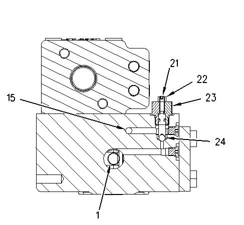
As seat (21) is turned counterclockwise, ball (24) will shift. As ball (24) is shifted, oil is allowed to flow through port (1) and valve (22) to port (15). Oil from the head end of the cylinder flows through port (15) to the hydraulic tank. This allows the boom to lower.