Small Displacement Change Operation
|
|
|
|
|
|
| Illustration 1 | g00820789 |
|
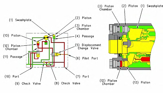
Travel motor (partial diagram) (1) Swashplate (2) Piston (3) Piston chamber (4) Passage (5) Displacement change valve (6) Port (pilot system oil pressure) (7) Port (supply oil or return oil) (8) Check valve (9) Check valve (10) Port (supply oil or return oil) (11) Passage (12) Piston chamber (13) Piston |
|
|
|
|
|
|
|
| Illustration 2 | g00675199 |
|
Small displacement change operation (1) Swashplate (2) Piston (3) Piston chamber (4) Passage (return oil) (5) Displacement change valve (6) Port (pilot system oil pressure) (7) Port (supply oil or return oil) (8) Check valve (9) Check valve (10) Port (supply oil or return oil) (11) Passage (pump delivery flow) (12) Piston chamber (13) Piston (14) Spool (15) Spring (16) Body (17) Spool chamber (18) Spool chamber (19) Passage (return oil) (20) Hydraulic tank |
|
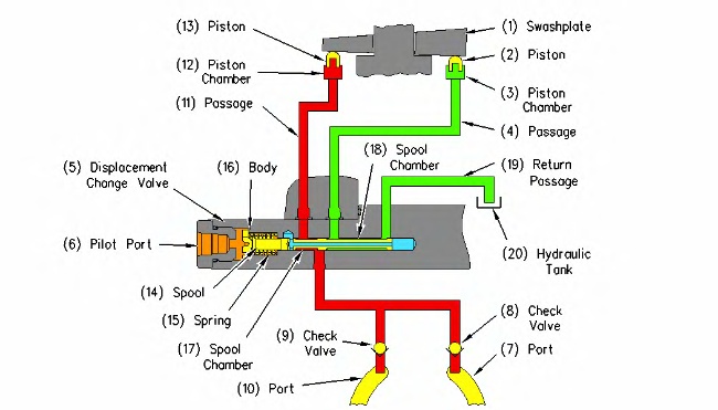
When the travel speed control switch on the control panel is pushed and the rabbit appears on the display, the machine is in HIGH SPEED MODE. In this condition, an input signal from the travel speed control switch is sent to the engine and pump controller. The pressure sensor for the pump delivery also provides an input signal to the engine and pump controller. When the travel load is light and when the pump delivery pressure is below a certain level, the output signal from the pressure sensor for the pump delivery is below a certain level. When the pump delivery pressure is below a certain level, the engine and pump controller energizes the travel speed solenoid. When the travel speed solenoid is energized, pilot system oil flows into pilot port (6) of displacement change valve (5). Spool (14) moves to the right against the force of spring (15) until the spool contacts body (16). Main pump oil flows from passage (7) of the travel motor through check valve (8). The main pump oil then flows through spool chamber (17) and passage (11) to piston chamber (12). The oil in piston chamber (12) moves piston (13) against swashplate (1). Swashplate (1) forces piston (2) into piston chamber (3). The oil in piston chamber (3) flows through passage (4), spool chamber (18) and passage (19) to hydraulic tank (20). As a result, the angle of swashplate (1) is decreased and the motor displacement is decreased. The travel speed is maximum in this condition.
Large Displacement Change Operation
|
|
|
|
|
|
| Illustration 3 | g00675334 |
|
Large displacement change operation (1) Swashplate (2) Piston (3) Piston chamber (4) Passage (return oil) (5) Displacement change valve (6) Port (pilot system oil pressure) (7) Port (supply oil or return oil) (8) Check valve (9) Check valve (10) Port (supply oil or return oil) (11) Passage (pump delivery flow) (12) Piston chamber (13) Piston (14) Spool (15) Spring (16) Body (17) Spool chamber (18) Spool chamber (19) Passage (return oil) (20) Hydraulic tank (21) Stopper (22) Center passage |
|
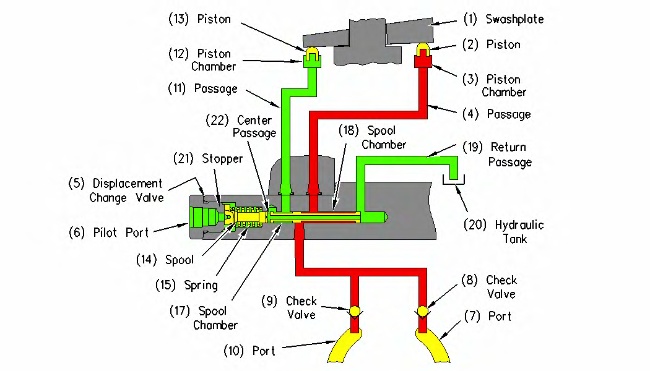
When the angle of swashplate (1) in the travel motor increases, the displacement of the travel motor increases. The angle of swashplate (1) in the travel motor will increase and the travel speed will decrease during the following two conditions.
- The angle of swashplate (1) in the travel motor will increase and the travel speed will decrease when an increase in pump pressure occurs.
When the machine is in HIGH SPEED MODE and the pump delivery pressure increases above a certain level, the engine and pump controller de-energizes the travel speed solenoid. When the travel speed solenoid is de-energized, pilot system oil stops flowing into pilot port (6) of displacement change valve (5). Spool (14) moves to the left by the force of spring (15) until the spool contacts stopper (21). Main pump oil flows from port (7) of the travel motor through check valve (8). The main pump oil then flows through spool chamber (18) and passage (4) into piston chamber (3). The oil in piston chamber (3) moves piston (2) against swashplate (1). The angle of swashplate (1) increases. Swashplate (1) forces piston (13) into piston chamber (12). The oil in piston chamber (12) flows through passage (11), spool chamber (17) and center passage (22) of spool (14). The oil then flows through passage (19) to hydraulic tank (20). As the angle of swashplate (1) increases, the displacement of the travel motor increases and the travel speed decreases.
- The angle of swashplate (1) in the travel motor will increase and the travel speed will decrease when the travel speed control switch is pushed in order to obtain LOW SPEED MODE.
When the travel speed control switch on the control panel is pushed and the tortoise appears on the display, the machine is in LOW SPEED MODE. In this condition, an input signal from the travel speed control switch is sent to the engine and pump controller. The engine and pump controller de-energizes the travel speed solenoid. The angle of swashplate (1) increases and the displacement of the travel motor increases. The travel speed decreases.