Construction
|
|
|
|
|
|
| Illustration 1 | g00875232 |
|
Main pumps (1) Proportional reducing valve (power shift pressure) (2) Case drain port (3) Outlet port (right pump) (4) Outlet port (left pump) (5) Outlet port (pilot pressure) (6) Port (negative flow control pressure for right pump) (7) Port (power shift pressure for right pump) (8) Port (pilot oil to proportional reducing valve) (9) Housing (10) Port (pressure sensor) (11) Inlet port (pilot pump) (12) Port (pressure sensor) (13) Right pump (14) Inlet port (supply oil from the hydraulic tank) (15) Left pump (16) Port (power shift pressure for left pump) (17) Port (negative flow control pressure for left pump) (71) Pilot pump |
|
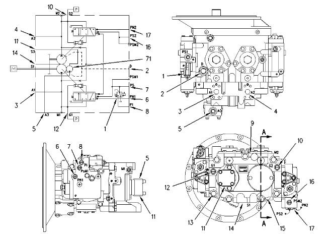
The main pumps consist of right pump (13) and left pump (15) . The right pump and the left pump are contained in an integral housing. Both pumps are variable displacement piston pumps. The right pump and the left pump are identical in construction and operation.
Supply oil from the hydraulic tank enters inlet port (14) . The single inlet port is common to both pumps. The right pump delivers oil through outlet port (3) . The left pump delivers oil through outlet port (4) . Supply oil for pilot pump (71) enters through inlet port (11) . The pilot pump delivers oil through outlet port (5) .
Both the right pump and the left pump have a regulator as part of the pump control system. The flow control of the pumps is performed by the operation of the regulators. The control system is identical for both pumps.
Proportional reducing valve (1) for the power shift pressure is located in the right pump regulator. The proportional reducing valve is controlled by the engine and pump controller. The proportional reducing valve controls the power shift signal for both the right pump and the left pump.
Negative flow control pressure from the main control valve enters the right pump regulator at port (6) . Negative flow control pressure from the main control valve enters the left pump regulator at port (17) .
Case drain oil from the pump housing flows from port (2) to the case drain filter.
Operation
|
|
|
|
|
|
| Illustration 2 | g00680303 |
|
Main pumps (sectional view) (4) Outlet port (left pump) (9) Housing (14) Inlet port (supply oil from the hydraulic tank) (15) Left pump (18) Gear (19) Drive shaft (20) Swashplate (21) Drive shaft (22) Gear (23) Plate (24) Retainer (25) Piston slipper (26) Pin (27) Piston (28) Barrel (29) Port plate (30) Passage (70) Port block (71) Pilot pump |
|
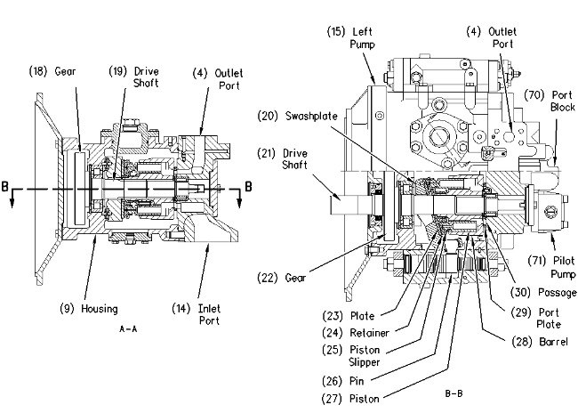
Gear (22) of drive shaft (21) meshes with gear (18) of drive shaft (19) . Gear (18) and gear (19) have the same number of teeth. Drive shaft (21) of right pump (13) is connected to the engine by a coupling. When the engine is running, drive shaft (19) and drive shaft (21) rotate at the same speed. Therefore, right pump (13) and left pump (15) rotate at the same speed.
Barrel (28) contains nine pistons (27) . Piston slippers (25) are connected to pistons (27) by retainers (24) . The piston slippers are pressed against plate (23) . Plate (23) lies on swashplate (20) . Barrel (28) is splined to drive shaft (21) . As drive shaft (21) rotates, the barrel, the pistons and the piston slippers rotate around swashplate (20) .
The angle of swashplate (20) determines the length of stroke of piston (27) . As the angle of the swashplate increases, the length of stroke of the pistons increases and the output flow of the pump increases. As piston slipper (25) rotates around the swashplate, the piston moves out of barrel (28) . The piston draws oil from passage (30) of port plate (29) during this movement. As the piston slipper continues to rotate around the swashplate, the piston moves into the barrel. The piston delivers oil to outlet port (5) during this movement. The oil delivery from ports (4) and (5) flows to the main control valve.