|
|
|
|
|
|
| Illustration 1 | g00909872 |
|
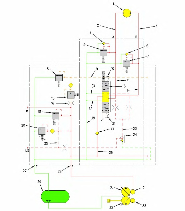
(1) Rotator motor (2) Line (3) Line (4) Makeup valve (5) Line relief valve (6) Makeup valve (7) Line relief valve (8) Relief valve (pilot) (9) Passage (10) Spring (11) Passage (12) Passage (return) (13) Spool (14) Passage (15) Flow control valve (16) Orifice (17) Passage (return) (18) Relief valve (differential) (19) Passage (return) (20) Relief valve (signal) (21) Spring (22) Check valve (23) Passage (load sensing) (24) Shuttle valve (25) Passage (load sensing) (26) Passage (supply) (27) Port (return) (28) Port (supply) (29) Hydraulic tank (30) Left pump (31) Auxiliary pump (32) Right pump (33) Pilot pump |
|
The medium pressure circuit is used for work tools that require rotation. Hydraulic shears and grapples are good examples.
Oil pressure is supplied from auxiliary pump (31) to the control valve. Auxiliary pump (31) is driven by left pump (30) .
Flow control valve (15) controls the amount of oil to pilot relief valve (8). The pilot oil in passage (9) is used to shift spool (13) .
Differential relief valve (18) controls the pressure in the rotator circuit. When spool (13) is in the NEUTRAL position, load signal pressure in passage (25) is low. Differential relief valve (18) will allow pump oil to return to the hydraulic tank.
|
|
|
|
|
|
| Illustration 2 | g00918661 |
|
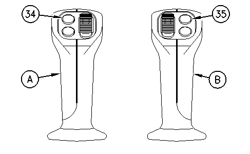
(A) Left joystick (B) Right joystick (34) Rotate counterclockwise (35) Rotate clockwise |
|
By depressing switch (34), the solenoid valve is energized. Pilot pressure in passage (9) shifts spool (13) downward against the force of spring (21). Oil flows from port (28) through passage (26) and check valve (22) to spool (13). The oil flows through spool (13), passage (14), and line (3) to rotator motor (1) .
Load signal pressure in passage (23) flows through shuttle valve (24) and passage (25) to differential relief valve (18). As the load signal pressure increases, differential relief valve (18) closes in order to increase the pump pressure to the rotator motor.
Hydraulic oil returns to hydraulic tank (29) from the motor through line (2), passage (11), spool (13), passage (17), passage (19), and port (27) .
Line relief valve (7) controls the oil pressure in the rotator circuit when the work tool is rotating counterclockwise.
To prevent cavitation in the rotator motor during a stop, makeup oil is supplied to the rotator motor. When switch (34) is released, oil from auxiliary pump (31) is blocked by spool (13). Since no oil delivery is supplied to rotator motor (1), the rotator motor will attempt to stop. However, the rotator motor will continue to rotate because of the inertia (weight and size) of the work tool. This causes a vacuum condition in line (3). The vacuum creates a pressure reduction in line (3) which allows oil to flow through makeup valve (6). This makeup oil prevents cavitation in the rotator circuit. The work tool will gradually stop.
Clockwise rotation functions in the same manner as counterclockwise rotation. When switch (35) is depressed the solenoid valve is energized and spool (13) shifts upward against the force of spring (10). Oil is sent through line (2) to rotator motor (1).

