|
|
|
|
|
|
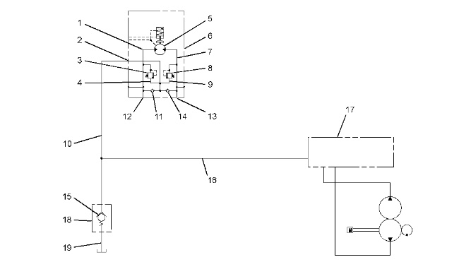
| Illustration 1 | g01355186 |
|
Pressure circuit for SWING RIGHT operation (partial schematic) (1) Passage (supply oil) (2) Makeup port (3) Relief valve (4) Passage (5) Motor rotary group (6) Swing motor (7) Passage (return oil) (8) Relief valve (9) Passage (10) Makeup line (11) Check valve (12) Port (supply oil) (13) Port (return oil) (14) Check valve (15) Check valve (16) Return line (17) Swing control valve (18) Slow return check valve (19) Return line |
|
|
|
|
|
|
|
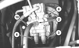
| Illustration 2 | g01696799 |
|
Swing motor (2) Makeup port (3) Relief valve (6) Swing motor (8) Relief valve (10) Makeup line |
|
|
|
|
|
|
|
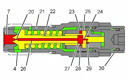
| Illustration 3 | g01231050 |
|
Swing relief valve (4) Return passage (7) Passage (20) Orifice (21) Spring (22) Spool (23) Piston chamber (24) Passage (25) Piston (26) Passage (27) Piston chamber (28) Orifice (29) Passage (30) Adjustment plug |
|
Relief valves (3) and (8) are located in the head of swing motor (6). These relief valves limit the pressure in the left and right swing circuits to the swing relief valve setting. This provides a cushion effect at a start or stop of the swing operation.
When the swing joystick is returned to the NEUTRAL position during the swing right operation, the swing control valve shifts to the NEUTRAL position. Since the swing control valve is in the NEUTRAL position, the oil delivery through port (12) to the motor rotary group (5) is now blocked at the swing control valve. The return oil from the motor rotary group through port (13) is also blocked at the swing control valve.
The mass (weight and size) of the upper structure causes the upper structure to attempt to continue to rotate after the swing joystick is returned to the NEUTRAL position. The motor rotary group is also attempting to continue to rotate. The motor rotary group attempts to draw oil through port (12) and attempts to displace the oil through port (13) .
The oil supply to motor rotary group (5) is insufficient. A vacuum condition occurs in passage (1). Return oil is supplied to the motor rotary group as makeup oil in order to prevent the vacuum condition. For more information concerning the makeup operation, refer to Systems Operation, “Oil Makeup (Swing System)”.
Since the flow of return oil from the motor rotary group through port (13) is blocked at the swing control valve, the pressure of the blocked oil in passage (7) increases. The increased oil pressure in passage (7) acts on swing relief valve (8). The increased pressure oil forces spool (22) of relief valve (8) to the right (open position) against the force of spring (21). When spool (22) shifts, oil flows through passage (9), check valve (11) and passage (1) to motor rotary group (5). The shock load is absorbed at the stop of a swing movement.
At swing relief valve (8), the increased oil pressure in passage (7) flows through orifice (20) in spool (22) and passage (26) to piston chamber (27). The force of spring (21) is less than the relief valve pressure setting. This causes spool (22) to move to the right (open position) before the oil pressure in passage (7) reaches the relief valve pressure setting. At the same time, the pressure oil in piston chamber (27) flows through passages (24) and (29). Piston (25) moves to the left against the force of spring (21). The oil in piston chamber (23) flows through orifice (28) and into piston chamber (27). Orifice (28) restricts the oil flow into piston chamber (27) .
The swing relief valve maintains the operating pressure of the swing hydraulic circuit at a lower pressure than the swing relief valve setting until the pressure in the swing hydraulic circuit forces piston (25) to the right against adjustment plug (30). When piston (25) contacts adjustment plug (30), the pressure in piston chamber (27) increases. The oil pressure in passage (7) reaches the swing relief valve setting. The oil in passage (7) flows around spool (22) and into return passage (4) .
After spool (22) begins to open and before piston (25) completes the movement to the left, the pressure in the swing hydraulic circuit increases gradually. The pressure in the swing hydraulic circuit does not reach a peak pressure. This is called a two-stage relief operation. The two-stage relief operation absorbs the shock load at the stop of a swing operation.
After the start of a swing right operation, the oil delivery from the idler pump flows through port (12) and passage (1) to motor rotary group (5). The mass (weight and size) of the upper structure causes an increase of oil pressure in passage (1). Spool (22) of swing relief valve (3) opens slightly. A portion of the high pressure oil in passage (1) flows through makeup port (2) to return line (19). This gives a smoother acceleration at the start of a swing operation.