Boom Raise (High Speed)
|
|
|
|
|
|
| Illustration 1 | g00915377 |
|
Hydraulic schematic for BOOM RAISE (high speed) (1) Line (oil flow to boom cylinder head end) (2) Boom cylinders (3) Boom lowering control valves (4) Check valve (5) Line (oil flow from boom cylinder rod end) (6) Line (oil flow to boom lowering control valve) (7) Return line (8) Line (9) Main control valve (10) Valve block (11) Check valve (12) Port (13) Parallel feeder passage (14) Return passage (15) Boom I control valve (16) Spring (17) Load check valve (18) Pilot control valve (boom and bucket) (19) Spring (20) Boom II control valve (21) Parallel feeder passage (22) Return passage (23) Pilot line (24) Pilot line (25) Port (26) Pilot line (27) Pilot line (28) Pressure reducing valve for boom priority (29) Left pump (30) Right pump (31) Pilot pump |
|

A BOOM RAISE operation at high speed is accomplished when the oil delivery from both left pump (29) and right pump (30) is supplied to the head end of boom cylinders (2). Boom I control valve (15) and boom II control valve (20) operate during the high speed operation. A BOOM RAISE operation at low speed is accomplished when the oil delivery from only right pump (30) is supplied to the head end of boom cylinders (2). During the low speed operation, boom I control valve (15) operates alone.
|
|
|
|
|
|
| Illustration 2 | g00915929 |
|
Main control valve compartment (15) Boom I control valve (20) Boom II control valve |
|

The oil delivery from right pump (30) flows through parallel feeder passage (21) in main control valve (9) to boom I control valve (15). The oil delivery from left pump (29) flows through parallel feeder passage (13) in main control valve (9) to boom II control valve (20) .
When the joystick for the boom is moved to the full BOOM RAISE position, the pilot oil flows from pilot control valve (18) through pilot line (26). The pilot oil flow then divides into two flow paths. Part of the pilot oil flows through pilot line (23) to port (12) of main control valve (9). The remainder of the pilot oil flows through pilot line (24) to port (25) of the main control valve.
A portion of the oil in pilot line (24) also flows through pilot line (27) to pressure reducing valve (28) for boom priority. During a combined operation of BOOM RAISE and STICK IN, the pilot oil flow to pressure reducing valve (28) for boom priority causes the boom circuit to receive oil flow priority. This allows the boom to raise at a high speed.
|
|
|
|
|
|
| Illustration 3 | g00915932 |
|
Boom I control valve (BOOM RAISE position) (16) Spring (17) Load check valve (21) Parallel feeder passage (22) Return passage (25) Port (32) Passage (33) Port (34) Port (35) Passage (36) Spool |
|

The pilot oil flow from port (25) shifts spool (36) of boom I control valve (15) against the force of spring (16). The oil delivery from the right pump in parallel feeder passage (21) flows through load check valve (17), passage (32), passage (35), port (33), and line (6) to boom lowering control valves (3). The oil delivery from the right pump then flows through check valves (4) and lines (1) to the head end of boom cylinders (2).
|
|
|
|
|
|
| Illustration 4 | g00915935 |
|
Boom II control valve (BOOM RAISE position) (11) Check valve (12) Port (13) Parallel feeder passage (19) Spring (37) Passage (38) Port (39) Spool (40) Passage |
|

The pilot oil flow in port (12) of boom II control valve (20) shifts spool (39) against the force of spring (19). The oil delivery from the left pump in parallel feeder passage (13) now flows through passage (37), passage (40), check valve (11) and flows out of port (38) to line (8). The oil delivery from the left pump combines with the oil delivery from the right pump at block valve (10). The combined pump oil flows through line (6) to boom lowering control valves (3) to the head end of boom cylinders (2) .
Note: The swing priority valve does not affect the boom II control valve.
Return oil from the rod end of boom cylinders (2) flows through line (5) to boom I control valve (15). The oil then flows through passage (22), return passage (14), and return line (7) to the hydraulic tank.
Boom Raise (Low Speed)
When the joystick for the boom is moved less than half of the travel distance for BOOM RAISE, low pilot oil pressure is supplied to boom I control valve (15) and boom II control valve (20) .
When the boom is raised at a low speed, boom I control valve (15) opens and boom II control valve (20) remains closed. The force of spring (16) in boom I control valve (15) is less than the force of spring (19) in boom II control valve (20). Because of the low pilot oil pressure, boom I control valve (15) will open and boom II control valve (20) will remain closed.
The oil delivery from right pump (30) now flows to the head end of boom cylinders (2). Without the oil delivery from left pump (29), the cylinder rod movement slows down when the boom is raised. The low speed operation of the boom is performed.
Boom Priority
|
|
|
|
|
|
| Illustration 5 | g00925865 |
|
Hydraulic schematic for BOOM RAISE and STICK OUT (2) Boom cylinders (18) Pilot control valve (boom and bucket) (28) Pressure reducing valve for boom priority (41) Stick cylinder (42) Pilot control valve (stick and swing) (43) Stick II control valve (44) Pilot line |
|
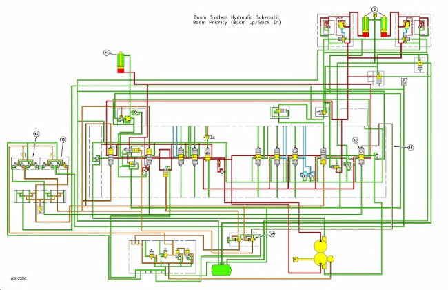
During combined operations of BOOM RAISE and STICK IN, the pilot oil pressure from pilot control valve (18) for the boom activates pressure reducing valve (28) for boom priority. Pressure reducing valve (28) for boom priority causes oil flow priority to the head end of the boom cylinders (2) during this combined hydraulic operation.
When the joystick for the stick is moved to the STICK IN position, a portion of the pilot oil from pilot control valve (42) for the stick flows through pressure reducing valve (28) for boom priority to stick II control valve (43). As the joystick for the boom is moved farther from the NEUTRAL position during a BOOM RAISE operation, pilot oil pressure from pilot control valve (18) for the boom increases. This gradual increase in pilot oil pressure causes the spool in pressure reducing valve (28) for the boom priority to gradually shift.
A portion of the pilot oil that flows to stick II control valve (43) from pilot control valve (42) for the stick is routed to the hydraulic tank. The pilot oil pressure in pilot line (44) that acts on stick II control valve (43) decreases. Stick II control valve (43) shifts toward the NEUTRAL position. The amount of oil flow from the main pumps to stick cylinders (41) decreases. This causes a greater portion of the oil flow from the main pumps to flow to the head end of the boom cylinders (2) .
Since the pilot oil pressure from pilot control valve (18) for the boom directly corresponds to the amount of movement or position of the joystick a gradual change to boom priority occurs. Thus, boom priority is controlled by the position of the joystick for the boom and boom priority automatically activates when the joystick reaches a certain position during a BOOM RAISE operation.
Boom Lower
|
|
|
|
|
|
| Illustration 6 | g00925866 |
|
Hydraulic schematic for BOOM LOWER (1) Line (oil flow from boom cylinder head end) (2) Boom cylinders (3) Boom lowering control valves (5) Line (oil flow to boom cylinder rod end) (6) Line (oil flow from boom lowering control valve) (10) Valve block (15) Boom I control valve (17) Load check valve (18) Pilot control valve (boom and bucket) (20) Boom II control valve (21) Parallel feeder passage (22) Return passage (29) Left pump (30) Right pump (31) Pilot pump (45) Valve (46) Passage (47) Valve (48) Pilot line (49) Pilot line (50) Flow control valve (51) Solenoid valve (SmartBoom) (52) Pilot line (53) Port (54) Passage (55) Center bypass passage (56) Boom regeneration valve (57) Pilot line (58) Negative flow control line (59) Orifice (60) Orifice (61) Spring |
|

During a BOOM LOWER operation, the oil delivery from only right pump (30) is supplied to boom cylinders (2) through boom I control valve (15). Boom I control valve (15) operates alone. Boom II control valve (20) is not operational in the BOOM LOWER operation.
The BOOM LOWER operation contains a regeneration circuit. When the joystick for the boom is moved to the BOOM LOWER position, orifice (59) in boom I control valve (15) and boom regeneration valve (56) are operational in the boom hydraulic circuit. The return oil flow from the head end of boom cylinders (2) flows through boom regeneration valve (56) to the rod end of the boom cylinders. The boom regeneration valve is described later in this section.
When the joystick for the boom is moved to the BOOM LOWER position, pilot oil from pilot control valve (18) flows through pilot line (57). The pilot oil flow then divides into three flow paths. Part of the pilot oil flows through pilot line (49), solenoid valve (51), and flow control valve (50) to boom I control valve (15). Part of the pilot oil flows through pilot line (52) to boom regeneration valve (56). The remainder of the pilot oil flows through pilot line (48) to boom lowering control valves (3) .
Since the pilot oil pressure has caused the spool in boom I control valve (15) to shift against the force of spring (61), the oil delivery from the right pump that flows through center bypass passage (55) is restricted by orifice (59). The negative flow control pressure in negative flow control line (58) decreases. The right pump upstrokes because of the negative flow control operation.
Reference: For more information concerning the negative flow control operation, refer to Systems Operation, “Negative Flow Control”.
|
|
|
|
|
|
| Illustration 7 | g00916884 |
|
Boom I control valve (BOOM LOWER position) (17) Load check valve (21) Parallel feeder passage (22) Return passage (33) Port (34) Port (36) Spool (53) Port (59) Orifice (60) Orifice (61) Spring (62) Passage |
|

The pilot oil flow from port (53) shifts spool (36) in boom I control valve (15) against the force of spring (61). The oil delivery from the right pump in parallel feeder passage (21) flows through load check valve (17), passage (62) and port (34). The oil delivery from the right pump then flows through line (5) to the rod end of boom cylinders (2) .
The return oil from the head end of boom cylinders (2) flows through line (1) into boom lowering control valves (3). Pilot pressure in pilot line (48) shifts valves (47) open. The return oil pressure in line (1) shifts valves (45) open. The return oil in line (1) flows through valves (45), passages (46), and valves (47) to line (6). The return oil then flows through line (6) and valve block (10) to passage (54) .
A portion of the return oil flows into port (33) of boom I control valve (15). The return oil flow is restricted by orifice (60). The return oil pressure in passage (54) increases. Most of the return oil flows through boom regeneration valve (56). The return oil is combined with the oil delivery from the right pump. The combined oil flow is supplied to the rod end of the boom cylinders through line (5) .
Boom Regeneration Valve
|
|
|
|
|
|
| Illustration 8 | g00916919 |
|
Boom regeneration valve (slow boom down) (9) Main control valve (63) Pilot port (64) Passage (65) Check valve (66) Spool (boom regeneration valve) (67) Passage |
|

|
|
|
|
|
|
| Illustration 9 | g00916921 |
|
Boom regeneration valve (slow boom down) (9) Main control valve (63) Pilot port (64) Passage (65) Check valve (66) Spool (boom regeneration valve) (67) Passage |
|

The boom hydraulic circuit contains a regeneration circuit. This regeneration circuit allows the return oil from the head end of the boom cylinders to be supplied to the rod end of the boom cylinders during the BOOM LOWER operation.
When the joystick for the boom is moved to the BOOM LOWER position, pilot oil flow from pilot control valve (18) enters pilot port (63). Spool (66) in the boom regeneration valve shifts downward. The return oil from the head end of the boom cylinders flows through passage (67) and through the throttling slots on the spool for the boom regeneration valve to check valve (65). Check valve (65) opens and the return oil flows through passage (64). The return oil from the head end of the boom cylinders in passage (64) combines with the oil delivery from the right pump. This combined oil now flows to the rod end of the boom cylinders.
The oil delivery from only the right pump is used for the BOOM LOWER operation. Since the boom regeneration valve supplies return oil from the head end to the rod end of the boom cylinders, more efficient use of the oil delivery from the right pump is achieved during a BOOM LOWER operation.
SmartBoom Operation
|
|
|
|
|
|
| Illustration 10 | g00915786 |
|
SmartBoom (DOWN mode) (1) Line (oil flow from boom cylinder head end) (2) Boom cylinders (3) Boom lowering control valves (5) Line (oil flow to boom cylinder rod end) (6) Line (oil flow from boom lowering control valve) (10) Valve block (15) Boom I control valve (18) Pilot control valve (boom and bucket) (29) Left pump (30) Right pump (31) Pilot pump (45) Valve (47) Valve (48) Pilot line (49) Pilot line (50) Flow control valve (51) Solenoid valve (SmartBoom) (56) Boom regeneration valve (57) Pilot line (68) Check valve (69) Check valve (70) Line (71) Pressure switch (72) Return line |
|
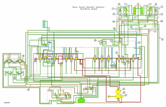
When the switch for the SmartBoom is in the DOWN mode, no pump oil is used to lower the boom. The boom will lower by the weight of the boom and the load.
Solenoid valve (51) and check valve (69) are energized when the switch for SmartBoom is in the DOWN mode. When pilot control valve (18) is moved to the DOWN position, pilot oil flows through line (57) to pilot lines (48) and (49) .
Solenoid valve (51) blocks the pilot oil in line (49) to boom I control valve (15). The boom I control valve remains in the NEUTRAL position. The pilot oil in line (49) also shifts boom regeneration valve (56) to the right.
Pilot oil in line (48) shifts valves (47) to the OPEN position. This will allow return oil from the head end of the boom cylinders to flow through line (1), and boom lowering control valves (3) to line (6). Because boom I control valve (15) is in the NEUTRAL position, the return passage in the main control valve is blocked. Since check valve (69) is energized, the oil from the head end of the boom cylinders will flow through line (70), check valve (69), and line (72) to the hydraulic tank. The boom will lower by the weight of the boom.