|
|
|
|
|
|
| Illustration 1 | g00681573 |
|
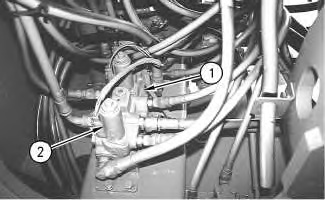
Pilot Oil Manifold (1) Pilot oil manifold (2) Hydraulic lockout solenoid valve |
|
|
|
|
|
|
|
| Illustration 2 | g00820055 |
|
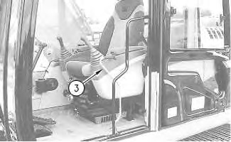
Cab (3) Hydraulic lockout lever (LOCKED position) |
|
|
|
|
|
|
|
| Illustration 3 | g00820057 |
|
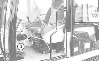
Cab (3) Hydraulic lockout lever (UNLOCKED position) |
|
|
|
|
|
|
|
| Illustration 4 | g01354346 |
|
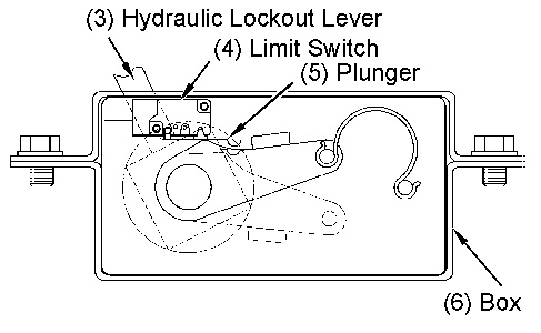
(3) Hydraulic lockout lever (4) Limit switch (5) Plunger (6) Box |
|
|
|
|
|
|
|
| Illustration 5 | g00773160 |
|
Cab (Bottom View) (6) Box |
|
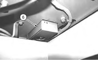
Limit switch (4) and plunger (5) are contained in box (6). The limit switch is activated by hydraulic lockout lever (3) .
When hydraulic lockout lever (3) is shifted to the LOCKED position, solenoid valve (2) of pilot oil manifold (1) is not energized. Pilot oil is not supplied to the pilot control valves. Thus operating the joysticks and/or the travel levers/pedals will not activate the cylinders or the motors.
The engine will not start unless hydraulic lockout lever (3) is in the LOCKED position. If some one unexpectedly operates the machine, the machine will not operate.
When hydraulic lockout lever (3) is placed in the UNLOCKED position, solenoid valve (2) is energized and pilot oil passes through the solenoid valve. Pilot oil now flows to the pilot control valves.
|
|
|
|
|
|
| Illustration 6 | g01218100 |
|
Partial Diagram of Hydraulic Lockout Solenoid Valve (UNLOCKED Circuit) (2) Hydraulic lockout solenoid valve (7) Solenoid (8) Spring (9) Spool (10) Control valve (11) Passage (12) Passage (13) Passage (14) Passage (return oil) (15) Passage (pilot oil to swing parking brake solenoid) (16) Swing parking brake solenoid (17) Pilot oil flow to pilot valves (joysticks) (18) Valve (hydraulic lockout) (19) Passage |
|
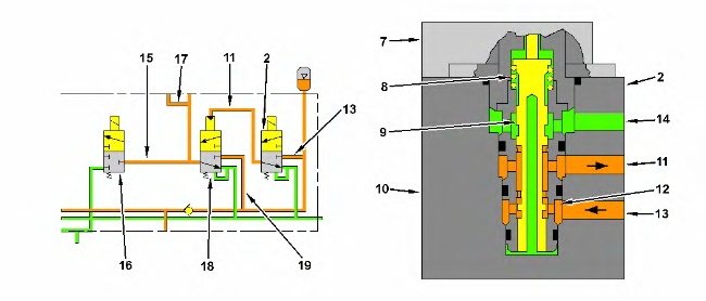
When hydraulic lockout lever (3) is placed in the UNLOCKED position, plunger (5) of limit switch (4) is depressed by control lever (3). Limit switch (4) is in the ON state.
The hydraulic lockout solenoid valve (2) consists of solenoid (7) and control valve (10). When hydraulic lockout lever (3) is in the UNLOCKED position, solenoid (7) controls valve (10). When solenoid (7) is energized, spool (9) moves in a downward direction against the force of spring (8). Passage (12) opens. Pilot pressure oil from passage (13) flows through passage (11) to valve (18). The spool in valve (18) moves in a downward direction. Pilot pressure oil in passage (19) flows through valve (18). Pilot oil is now delivered through passage (15) to swing parking brake solenoid (16). Pilot pressure oil in passage (19) is also delivered to the pilot control valves (joysticks and travel levers/pedals) through line (17).
|
|
|
|
|
|
| Illustration 7 | g01218083 |
|
Partial Drawing of Hydraulic Lockout Solenoid Valve (LOCKED Position) (1) Hydraulic lockout solenoid valve (7) Solenoid (8) Spring (9) Spool (11) Passage (12) Passage (13) Passage (14) Passage (return oil) (20) Passage |
|
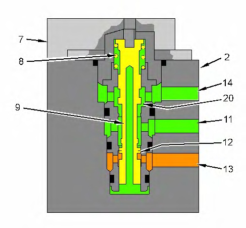
When hydraulic lockout lever (3) is moved to the LOCKED position, plunger (5) of limit switch (4) is not depressed by control lever (3). Limit switch (4) is in the OFF state.
When hydraulic lockout lever (3) is in the LOCKED position, solenoid (7) is not energized. Spool (9) is forced upward by spring (8). Passage (20) opens and passage (12) closes. Passage (13) is not open to passage (11). Pilot oil supply to line (17) is stopped. Pilot oil supply to the pilot control valves (joysticks and travel levers/pedals) is blocked. The cylinders and the motors can not be activated.