|
|
|
|
|
|
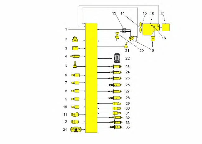
| Illustration 1 | g03367609 |
|
(1) Machine ECM (2) Engine speed dial (3) Switch panel (4) Clench pressure sensor (attachment) (5) Manual low idle switch (6) Implement pressure switch (7) Swing pressure switch (8) Right travel pressure switch (9) Left travel pressure switch (10) Straight travel pressure switch (11) Drive pump pressure sensor (12) Idler pump pressure sensor (13) Fuse panel (14) Viscous clutch (15) Fan speed sensor (16) Engine (17) Main pumps (18) Engine speed pickup (19) Battery (20) Engine start switch (21) Backup switch (22) Monitor (23) Heavy lift solenoid valve (If Equipped) (24) Straight travel solenoid valve (25) Travel speed solenoid valve (26) Swing brake solenoid valve (27) Hydraulic lockout solenoid (28) Flow limiter valve (attachment pump) (29) Pressure switch (attachment pump) (30) Attachment pedal pressure switch (Left) (31) Attachment pedal pressure switch (Right) (32) Proportional reducing valve for auxiliary hydraulics (33) Power shift solenoid valve (34) Fine swing switch (If Equipped) (35) Heavy lift solenoid valve (If Equipped) |
|
|
|
|
|
|
|
| Illustration 2 | g01173858 |
|
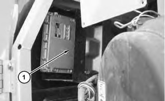
(1) Machine ECM |
|
|
|
|
|
|
|
| Illustration 3 | g01173869 |
|
(22) Monitor |
|

The electronic control system consists of monitor (22) in the cab and the machine ECM (1) that is located in the compartment behind the cab. The electronic control system controls the engine speed and the pumps through the machine ECM.
Machine ECM (1) receives input signals from various components on the machine. The machine ECM continuously monitors the input signals to control the output flow rate of the main pumps, engine speed, and various components of the machine hydraulic systems.
The machine ECM has the following three major functions.
- The electronic control system controls the output flow rate of the main pumps. The machine ECM sends an electrical signal to the power shift solenoid that is based on engine speed and the position of the engine speed dial. This signal allows the main pumps to supply the optimum output that matches the hydraulic load to the machine and the engine speed. When a large load is placed on the machine, the system allows the pumps to destroke. The system utilizes the available maximum engine horsepower.
- The electronic control system controls the engine speed, Automatic Engine Speed Control (AEC). When there is a small load condition or no load condition, the system automatically decreases the engine speed. The AEC system is designed to reduce fuel consumption and noise.
- The electronic control system controls various components of the machine hydraulic systems. The machine ECM sends output signals to the swing brake solenoid valve, the travel speed solenoid valve and the straight travel solenoid.
Note: If a problem occurs in the ECM, temporary operation of the machine is possible by using the backup switches located in the cab. For more information concerning the backup system, refer to Operation and Maintenance Manual, “Backup Controls”.
ReferenceFor more information concerning the operation of the electronic control system, refer to Systems Operation/Testing and Adjusting, “Machine Electronic Control System”.