|
|
|
|
|
|
| Illustration 1 | g01309786 |
|
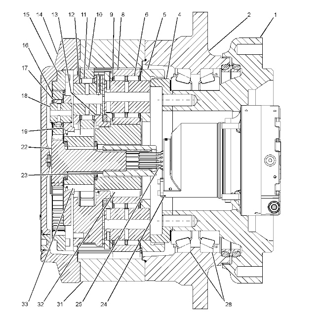
Final Drive (1) Spindle housing (2) Sprocket housing (4) Ring gear (5) Planetary carrier (third stage) (6) Roller bearing (8) Planetary gear (third stage) (9) Shaft (10) Planetary gear (secondary stage) (11) Roller bearing (12) Shaft (13) Planetary carrier (second stage) (14) Cover (15) Ring gear (16) Planetary gear (first stage) (17) Roller bearing (18) Shaft (19) Planetary carrier (first stage) (22) Sun gear (first stage) (23) Coupling (24) Travel motor (25) Output shaft (travel motor) (28) Roller bearings (31) Ring gear (second stage and third stage) (32) Sun gear (third stage) (33) Sun gear (second stage) |
|
The final drive reduces the rotational speed of travel motor (24). Output shaft (25) of travel motor (24) is splined to coupling (23). Coupling (23) is splined to sun gear (22) .
The final drive consists of two groups. The first group consists of the three stages of the planetary gear reduction. The second group is the output group.
- The first stage reduction group consists of the following components: sun gear (22), planetary gear (16), planetary carrier (19) and ring gear (15). The group for second stage reduction consists of the following components: sun gear (33), planetary gear (10), planetary carrier (13) and ring gear (31). The third stage reduction group consists of the following components: sun gear (32), planetary gear (8), planetary carrier (5) and ring gear (31) .
- The output group is described in the following manner. The rotation of drive sprocket housing (2) drives the track. Drive sprocket housing (2) and ring gear (31) are connected by bolts. Cover (14) is bolted to ring gear (31). The drive sprocket housing, the ring gear and the cover are supported by roller bearings (28). This planetary assembly rotates with ring gear (31) .
The planetary gears reduce the travel speed. The travel speed is reduced by the ratio of teeth of the sun gear and the ring gear. The compact final drive offers a greater reduction ratio when the sun gear is incorporated inside the ring gear.
Operation
Sun gear (22) is splined to coupling (23). Output shaft (25) of travel motor (24) is splined to coupling (23). The rotation of output shaft (25) is transmitted to sun gear (22) by coupling (23). When sun gear (22) rotates clockwise, the final drive operates in the following manner.
|
|
|
|
|
|
| Illustration 2 | g01675245 |
|
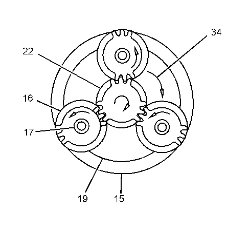
First Stage Reduction Group (15) Ring gear (16) Planetary gear (first stage) (17) Roller bearing (first stage) (19) Planetary carrier (first stage) (22) Sun gear (first stage) (34) Rotational direction (first stage reduction group) |
|
In the first stage reduction group, sun gear (22) causes planetary gears (16) to rotate counterclockwise. Planetary gears (16) mesh with sun gear (22) and ring gear (15). Planetary gears (16) rotate around sun gear (22) and the internal teeth of ring gear (15). Each planetary gear (16) is mounted to planetary carrier (19) by shafts (18) and by roller bearings (17) in order to form a planetary assembly. Planetary carrier (19) rotates in a clockwise direction (34).
|
|
|
|
|
|
| Illustration 3 | g01675248 |
|
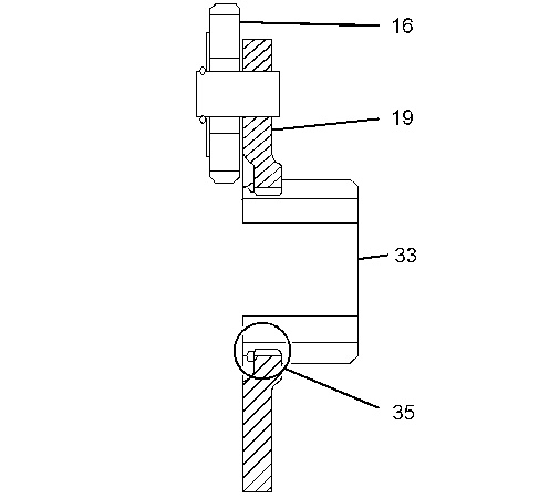
Engagement of Splines (16) Planetary gear (first stage) (19) Planetary carrier (first stage) (33) Sun gear (second stage) (35) Engagement of splines |
|
The splines of first stage planetary carrier (19) mesh with second stage sun gear (33). The rotation of planetary carrier (19) is transmitted to sun gear (33). Sun gear (33) rotates clockwise.
|
|
|
|
|
|
| Illustration 4 | g01675250 |
|
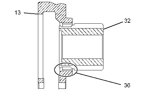
Engagement of Splines (13) Planetary carrier (second stage) (32) Sun gear (third stage) (36) Engagement of splines |
|
In the group for second stage reduction, sun gear (33) causes planetary gears (10) to rotate counterclockwise. Planetary gears (10) mesh with sun gear (33) and ring gear (31). Planetary gears (10) rotate around sun gear (33) and the internal teeth of ring gear (31). Each planetary gear (10) is mounted to planetary carrier (13) by shafts (12) and by roller bearings (11) in order to form a planetary assembly. Planetary carrier (13) rotates clockwise.
The spline of second stage planetary carrier (13) meshes with third stage sun gear (32). The rotation of planetary carrier (13) is transmitted to sun gear (32). Sun gear (32) rotates clockwise.
In the third stage reduction group, the spline teeth of planetary carrier (5) mesh with teeth on the outer circumference of ring gear (4). Ring gear (4) is bolted to spindle housing (1). Since spindle housing (1) is fixed to the track frame, planetary carrier (5) does not rotate.
Planetary carrier (5) is stationary. The planetary gear (third stage) (8) rotates ring gear (31). Since planetary carrier (5) is attached to the track frame and the planetary carrier does not move, ring gear (31) rotates counterclockwise. Since ring gear (31) and drive sprocket housing (2) are held together with bolts, drive sprocket housing (2) rotates counterclockwise. This causes the right track to move in a forward direction.


