|
|
|
|
|
|
| Illustration 1 | g01242804 |
|
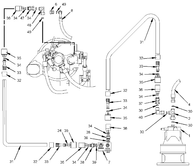
Flow meter tool layout (1) Swing motor (2) Connector at swing motor (3) 6V-9840 Swivel tee (4) Makeup line (swing motor) (6) 6V-9509 Face seal plug (7) 4C-9910 Portable hydraulic tester (flow meter) (8) Pilot line (delivery line from the pilot pump) (9) Connector at pilot pump (10) Pilot filter (14) Pilot pump (30) 5K-9090 O-Ring seal (31) 5P-0201 Hose (32) 5P-1010 Sleeve (33) 4C-8767 Coupling (34) 7M-8485 O-Ring seal (35) 4C-6481 Coupler assembly (36) 4C-6482 Nipple assembly (37) 4I-6141 Coupling (38) 8C-9026 Adapter (39) 6K-6307 O-Ring seal (40) 6V-9854 Swivel elbow (47) 4I-6140 Coupling (48) 8C-8762 Elbow (49) 6V-8398 O-Ring seal |
|
|
To prevent personal injury or equipment damage from failure of the hydraulic test equipment or associated circuit components because of blocked pump flow, make sure that the test equipment valves are fully open before starting the engine. |
|
|
| NOTICE |
|---|
|
Care must be taken to ensure that fluids are contained during performance of inspection, maintenance, testing, adjusting and repair of the product. Be prepared to collect the fluid with suitable containers before opening any compartment or disassembling any component containing fluids. Refer to Special Publication, NENG2500, “Caterpillar Dealer Service Tool Catalog” for tools and supplies suitable to collect and contain fluids on Caterpillar products. Dispose of all fluids according to local regulations and mandates. |
|
|
- Position the machine on level ground.
- Stop the engine.
- Release the pressure in the hydraulic system. Refer to Testing and Adjusting, “Hydraulic System Pressure – Release”.
- Attach 311-1362 Vacuum Cap onto the hydraulic tank. Attach an air supply hose onto the assembly. Apply 276 to 414 kPa (40 to 60 psi). This procedure will pull a vacuum on the hydraulic system.
- Install the following tools in accordance with the flow meter tool layout and the circuit diagram. Refer to Illustration 1 and Illustration 2.
- Install multitach group (13) on engine (12) .
- Remove pilot line (8) from connector (9) at pilot pump (14) .
- Install seal (49) and plug (6) to the end of pilot line (8) .
- Install seal (49) and elbow (48) to connector (9) at pilot pump (14) .
- Install seal (34), coupling (47), seal (34) and nipple assembly (36) to elbow (48) .
- Disconnect makeup line (4) from connector (2) at swing motor (1) .
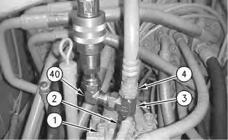
Illustration 3 g00669270 Swing motor
(1) Swing motor
(2) Connector
(3) Tee
(4) Makeup line
(40) Elbow
- Assemble and install seals (30), tee (3), swivel elbow (40) and coupling (37) to connector (2) at swing motor (1) .
- Remove 311-1362 Vacuum Cap and install the filler plug for the hydraulic tank.
- Connect portable hydraulic tester (7) and test hoses between nipple assembly (36) at the pilot pump and coupling (37) at the swing motor.
|
|
|
|
|
|
| Illustration 2 | g01186284 |
|
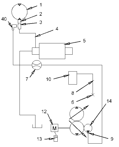
Circuit diagram (1) Swing motor (2) Connector (3) Tee (4) Makeup line (5) Main control valve (6) Plug (7) Portable hydraulic tester (8) Pilot line (9) Connector at pilot pump (10) Pilot filter (12) Engine (13) Multitach group (14) Pilot pump (40) Elbow |
|
- Start the engine.
- Place the machine controls at the following settings: engine speed dial “10” and AEC switch OFF. Refer to Testing and Adjusting, “Engine Performance – Test (Engine Speed)” for engine rpm settings.
- Increase the hydraulic oil temperature to 55° ± 5°C (131° ± 9°F).
- Turn valve (16) on portable hydraulic tester (7) clockwise until the pressure gauge on the portable hydraulic tester shows a reading of 3900 kPa (565 psi).
|
|
|
|
|
|
| Illustration 4 | g00344084 |
|
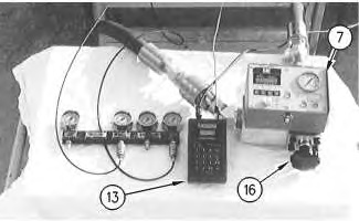
Portable hydraulic tester (flow meter) (7) Portable hydraulic tester (flow meter) (13) Multitach group (16) Valve (flow meter) |
|
- Record the pilot pump flow at 4100 ± 200 kPa (595 ± 29 psi) in Table 1.
| Pump Flow Test | ||
|---|---|---|
| Oil Temperature C° (F°) | ||
| Engine Speed (rpm) | ||
| Flow Measured liter/min (US gpm) | ||
| Flow Corrected liter/min (US gpm) | ||
| Specification for Pump Flow liter/min (US gpm) | New | 40.1 (11) |
| Service Limit | 33 (8.7) | |
Note: Specifications for pump flow are based on an engine speed of 1800 rpm. To get more accurate test results, measured flow should be corrected by the following calculation.
| Corrected flow | = | Measured flow x 1800 rpm | |||
| Measured rpm | |||||
Flow measurements must be done in pressure rise.