|
|
|
|
|
|
| Illustration 1 | g02483656 |
|
(19) Return filter (25) Hydraulic tank (34) Element (35) Return chamber (36) Tank chamber (37) Suction filter (38) Line (39) Suction line (40) Port (41) Relief valve (42) Passage |
|
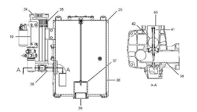
The return oil from the hydraulic oil cooler flows through port (40) and passage (42) to return chamber (35) .
Return filter (19) consists of element (34) and relief valve (41) . The return filter is mounted on the rear surface of the hydraulic tank.
The return oil passes through element (34) of return filter (19) . The return oil then flows through line (38) to hydraulic tank (25) . Thereafter, the oil passes through suction filter (37) and the oil is delivered to the pumps through suction line (39) .
|
|
|
|
|
|
| Illustration 2 | g02483657 |
|
(43) Air breather |
|
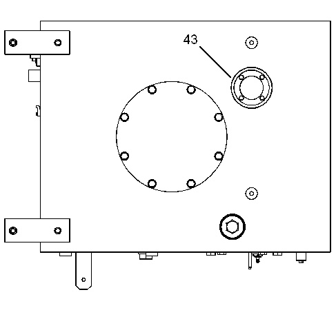
Air breather (43) is located on the upper surface of the hydraulic tank. The air breather prevents an increase or a decrease of air pressure in the hydraulic tank regardless of the following circumstances :
- Change of air pressure in the hydraulic tank due to cylinder movement.
- Change of air pressure in the hydraulic tank capacity due to a temperature change.