- Position the machine on level ground and stop the engine.
- Release the pressure in the hydraulic system. Refer to Testing and Adjusting, “Hydraulic System Pressure – Release”.
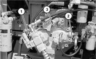
- Attach a 60000 kPa (8700 psi) pressure gauge to pressure tap (1) and pressure tap (2) .
|
|
|
|
|
|
| Illustration 1 | g01266656 |
|
Pump compartment (1) Pressure tap (delivery pressure for drive pump) (2) Pressure tap (delivery pressure for idler pump) (3) Pressure tap (power shift pressure) |
|
- Start the engine.
- Place the machine controls at the following settings: engine speed dial “10” and AEC switch OFF. Refer to Testing and Adjusting, “Engine Performance – Test (Engine Speed)” for engine rpm settings.
- Increase the hydraulic oil temperature to 55° ± 5°C (131° ± 9°F).
- Open the bucket until the bucket cylinder rod is at the full retraction.
- Check the main relief valve pressure setting at pressure tap (1) or pressure tap (2) .
- Return the control lever to the NEUTRAL position. Adjust the main relief valve pressure to 35000 + 500 – 1000 kPa (5076 + 73 – 145 psi).
|
|
|
|
|
|
| Illustration 2 | g01241266 |
|
Top of main control valve (4) Adjustment screw (5) Locknut (6) Main relief valve |
|
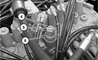
- To adjust the main relief valve pressure, loosen locknut (5) and turn adjustment screw (4) until the pressure gauge reading at pressure tap (2) is 35000 + 500 – 1000 kPa (5076 + 73 – 145 psi).
- Tighten locknut (5) to a torque of 50 ± 10 N·m (37 ± 7 lb ft).
Note: Turning adjustment screw (4) clockwise increases the pressure. Turning adjustment screw (4) counterclockwise decreases the pressure.
Note: Always make final pressure adjustments on pressure rise.
Temporary Setting of the Main Relief Valve
Note: A temporary setting of the main relief valve is required before any line relief valve can be adjusted.
- Position the machine on level ground.
|
|
|
|
|
|
| Illustration 3 | g01266656 |
|
Pump compartment (1) Pressure tap (delivery pressure for drive pump) (2) Pressure tap (delivery pressure for idler pump) (3) Pressure tap (power shift pressure) |
|
- Stop the engine.
- Release the pressure in the hydraulic system. Refer to Testing and Adjusting, “Hydraulic System Pressure – Release”.
- Connect a 60000 kPa (8700 psi) pressure gauge to pressure tap (1) and pressure tap (2).
- Start the engine.
- Increase the hydraulic oil temperature to 55° ± 5°C (131° ± 9°F).
- Place the machine controls at the following settings: engine speed dial “10” and AEC switch OFF. Refer to Testing and Adjusting, “Engine Performance – Test (Engine Speed)” for engine rpm settings.
- Open the bucket until the bucket cylinder rod is at the full retraction.
- Check the main relief valve pressure setting at pressure tap (1) or pressure tap (2) .
- Be sure that the main relief valve pressure is set at 35000 + 500 – 1000 kPa (5076 + 73 – 145 psi).
|
|
|
|
|
|
| Illustration 4 | g01241266 |
|
Top of main control valve (4) Adjustment screw (5) Locknut (6) Main relief valve |
|
- Loosen locknut (5). Turn adjustment screw (4) clockwise for one half turn. Tighten locknut (5) .
Note: Always make final pressure adjustments on pressure rise.