Specification
| “Relief Valve (Pilot) – Test and Adjust” | ||
|---|---|---|
| Machine Settings | Engine Speed | |
| Speed Dial “10” AEC switch OFF |
||
| Item | Specification | Actual |
| Pilot relief valve pressure | 4100 ± 200 kPa (595 ± 29 psi) | |
Introduction
The pilot relief valve is located on the mounting base for the pilot oil filter. The pilot relief valve limits the pressure in the pilot system. The pilot relief valve setting is adjustable.
Required Tools
|
|
|
|
|
|
| Illustration 1 | g01623868 |
|
Tooling group “B” 198-4240 Digital Pressure Indicator Gp |
|
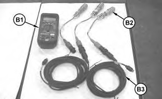
| Tool | Item | Part Number | Description | Qty |
|---|---|---|---|---|
| B | 198-4240 | Digital Pressure Indicator Gp | ||
| B1 | 198-4234 | Digital Pressure Indicator | 1 | |
| B2 | 198-4238 | Pressure Sensor 34,450 kPa (5000 psi) |
1 | |
| B3 | 198-4236 | Adapter Cable As | 1 | |
Machine Preparation
- Position the machine on level ground.
- Stop the engine.
- Release the pressure in the hydraulic system. Refer to Testing and Adjusting, “System Pressure – Release”.
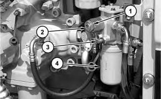
- Connect a 34,450 kPa (5000 psi) pressure sensor to pressure tap (3) .
|
|
|
|
|
|
| Illustration 2 | g01621986 |
|
Pilot oil manifold compartment (1) Locknut (2) Adjustment screw (3) Pressure tap (4) Pilot filter |
|
Test Procedure
- Start the engine.
- Place the machine controls at the following settings: engine speed dial “10” and AEC switch OFF. Refer to Testing and Adjusting, “Engine Performance – Test (Engine Speed)” for engine rpm settings.
- Increase the hydraulic oil temperature to 55° ± 5°C (131° ± 9°F).
- Check the pilot relief valve setting at pressure tap (3) . Refer to Table 1 for pilot relief pressure.
Adjustment Procedure
- In order to adjust the pilot relief valve, loosen locknut (1) .
- Turn adjustment screw (2) until the pressure reading at pressure tap (3) is within the specification.
Note: Turn adjustment screw (2) clockwise in order to increase the pressure. Turn adjustment screw (2) counterclockwise in order to decrease the pressure.
Note: Always make final pressure adjustments on pressure rise.
- Tighten locknut (1) to a torque of 49 ± 5 N·m (36 ± 4 lb ft).
- Test the pressure setting again. Refer to “Test Procedure”.
Note: Normal operation of the engine and pumps are necessary for the pressure adjustment. If the results of the pressure adjustments are not correct, then check the engine and the pump characteristic curve.