Specification
Note: Certain machines will default to “Economy Mode” at machine startup. Change to “High Hydraulic Power Mode” before performing the test procedure.
| “Travel on Level Ground – Test” | |||||
|---|---|---|---|---|---|
| Travel Time (time in seconds) | |||||
| Travel Speed | New | Rebuild | Service Limit | Actual | |
| HIGH | Forward | 15.2 or less | 16.2 or less | 17.2 or less | |
| Reverse | |||||
| LOW | Forward | 24.0 or less | 25.5 or less | 27.0 or less | |
| Reverse | |||||
| Travel Deviation (1) mm (inch) | |||||
| Travel Speed | New | Rebuild | Service Limit | Actual | |
| HIGH | Forward | 800 (31.5) or less | 1200 (47.2) or less | 1500 (59.1) or less | |
| Reverse | |||||
| LOW | Forward | 800 (31.5) or less | 1200 (47.2) or less | 1500 (59.1) or less | |
| Reverse | |||||
| ( 1 ) | Travel deviation (distance) from the reference line |
Introduction
The performance level of the travel motors can be determined with the following procedure.
Note: The engine speed and/or the machine configuration that is used during this test can affect the results of this test. Refer to Testing and Adjusting, “Engine Performance – Test (Engine Speed)” for the engine speed that was used for this test. Refer to Testing and Adjusting, “Operational Checks” for the machine configurations that were used for this test.
Note: The relief valve pressure settings must be set to the relief valve pressure specification before performing this operational check. Refer to Testing and Adjusting, “Specifications”.
Required Tools
| Required Tools | |
|---|---|
| Description | Qty |
| Measuring Tape | 1 |
| Stopwatch | 1 |
Machine Preparation
- Travel distance must be at least 25 m (82 ft) long. Travel test ground must be hard and as level as possible.
|
|
|
|
|
|
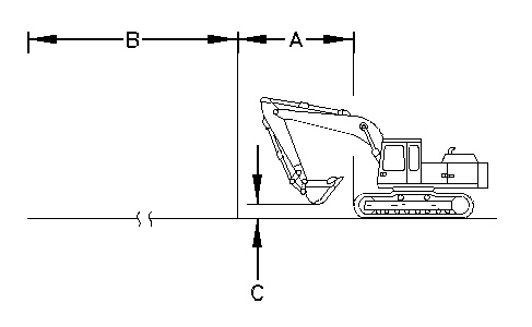
| Illustration 1 | g00296317 |
|
(A) Preliminary run 5 m (16.4 ft) (B) Travel distance 20 m (65.6 ft) (C) Bucket height 0.5 to 1 m (1.6 to 3.3 ft) |
|
- Draw a 25 m (82 ft) straight line on travel test ground as a reference line.
Test Procedure
- Start the engine.
- Place the machine controls at the following settings: Engine speed dial “10” and AEC switch OFF.
- Increase the hydraulic oil temperature to 55° ± 5°C (131° ± 9°F).
- The bucket should be empty.
- Position the machine so that one track is parallel with the reference line. Position the machine for the travel test. Refer to Illustration 1.
- Place the travel speed control switch in HIGH position.
- Move the machine by operating both travel levers at the same time.
- The first 5 m (16.4 ft) are for a preliminary run. Measure the travel time that is required to travel the remaining 20 m (65.6 ft). Measure the time that is required in each direction.
- Measure the travel deviation from the reference line.
- Place the travel speed control switch on the LOW position and repeat Steps 7 through 9.