Disassembly Procedure
Start By:
- Remove auxiliary hydraulic pump assembly. Refer to Disassembly and Assembly, “Auxiliary Hydraulic Pump – Remove”.
|
|
| NOTICE |
|---|
|
Failure to properly assemble parts or failure to follow established procedures can lead to damage of the parts and assembly. To avoid damage to parts, always identify and mark the parts so that they can be installed in the same location. Ensure that gear surfaces align. Never force parts during assembly. |
|
|
- Thoroughly clean the outside of the auxiliary hydraulic pump.
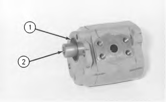
- Remove coupling (2) from the drive gear. Remove O-ring seal (1) from the end frame.
|
|
|
|
|
|
| Illustration 1 | g00536005 |
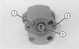
- Remove bolts (3) and separate end plate (4) from the center case.
- Remove square ring (7) and plate (9) from the center case.
Note: Note the position of plate (9) in the center case. The plate must be reinstalled in the plate’s original position.
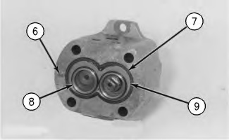
- If necessary, remove dowels (6) from the center case.
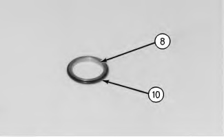
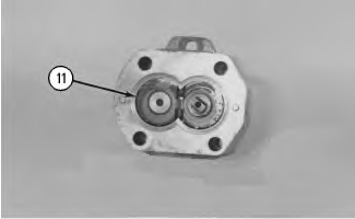
- Remove thrust plate (11) from the center case. Remove the bushings from thrust plate (11).
|
|
|
|
|
|
| Illustration 5 | g00535976 |
- Remove square ring (19), plate (18) and thrust plate (17) from the center case. Remove bushings (16) from thrust plate (17).
|
|
|
|
|
|
| Illustration 8 | g00535971 |
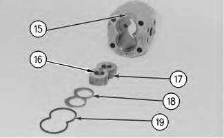
Note: Note the position of plate (18) and thrust plate (17) from the center case. The plate and the thrust plate must be installed in the original positions in the center case.
- If necessary, remove dowels (15) from the center case.