Removal Procedure
Note: Put identification marks on all hoses, on all hose assemblies, on all wires, and on all tube assemblies for installation purposes. Plug all hose assemblies and all tube assemblies. This helps to prevent fluid loss, and this helps to keep contaminants from entering the system.
Note: Put marks for orientation and location marks on all fittings for installation purposes.
|
|
| NOTICE |
|---|
|
Care must be taken to ensure that fluids are contained during performance of inspection, maintenance, testing, adjusting and repair of the product. Be prepared to collect the fluid with suitable containers before opening any compartment or disassembling any component containing fluids. Refer to Special Publication, NENG2500, “Caterpillar Tools and Shop Products Guide” for tools and supplies suitable to collect and contain fluids on Caterpillar products. Dispose of all fluids according to local regulations and mandates. |
|
|
|
Personal injury can result from hydraulic oil pressure and hot oil. Hydraulic oil pressure can remain in the hydraulic system after the engine has been stopped. Serious injury can be caused if this pressure is not released before any service is done on the hydraulic system. Make sure all of the work tools have been lowered to the ground, and the oil is cool before removing any components or lines. Remove the oil filler cap only when the engine is stopped, and the filler cap is cool enough to touch with your bare hand. |
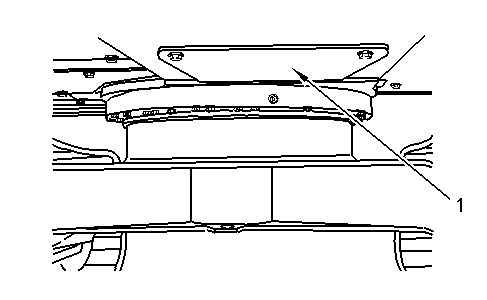
- Position the machine in order to gain access to bottom guard (1) .
|
|
|
|
|
|
| Illustration 1 | g00889074 |
|
Bottom guard (1) is located at the rear of the swing gear. |
|
- Release the hydraulic system pressure. Refer to Disassembly and Assembly, “Hydraulic System Pressure – Release”.
- Drain the hydraulic system into a suitable container for storage or disposal. Refer to Operation and Maintenance Manual, “Hydraulic System Oil – Change” for the proper procedure. Refer to Operation and Maintenance Manual, “Refill Capacities”.
- Remove bottom guard (1) in order to gain access to the control manifold.
- Disconnect hose assemblies (2) from main control valve (3) in order to facilitate the removal of the control manifold.
|
|
|
|
|
|
| Illustration 2 | g00888919 |
|
The above Illustration is from the top side of the machine. |
|
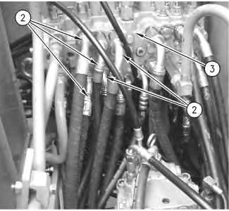
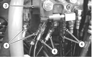
- Remove hose assemblies (4) from main control valve (3) in order to facilitate the removal of the control manifold.
|
|
|
|
|
|
| Illustration 3 | g00889193 |
|
The above Illustration is from the top side of the machine. |
|
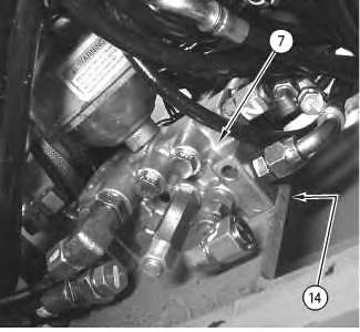
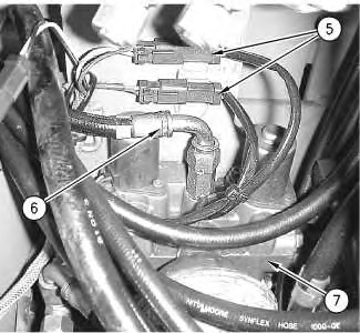
- Disconnect harness assemblies (5). Slide the connectors for harness assemblies (5) out of the mounting locations. Disconnect hose assembly (6) from control manifold (7) .
|
|
|
|
|
|
| Illustration 4 | g00889255 |
|
The above Illustration is taken from the top side of control manifold (7) . |
|
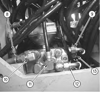
- Remove hose assemblies (8), (9), (10), (11), (12), and (13) from the bottom of the control manifold.
|
|
|
|
|
|
| Illustration 5 | g00889303 |
|
The above Illustration is taken from the underside of the machine. |
|